Power tool

Inactive Publication Date: 2016-04-21
HITACHI KOKI CO LTD
View PDF5 Cites 21 Cited by
  • Summary
  • Abstract
  • Description
  • Claims
  • Application Information

AI Technical Summary

Benefits of technology

[0062]The invention provides a power tool capable of preventing damage of a switching element while

Problems solved by technology

Thus, for example, when a power tool of 100 V specification is connected to a 200 V high voltage commercial power supply, the current value flowing through the mot

Method used


Image

  • Power tool
  • Power tool
  • Power tool

Examples


first embodiment

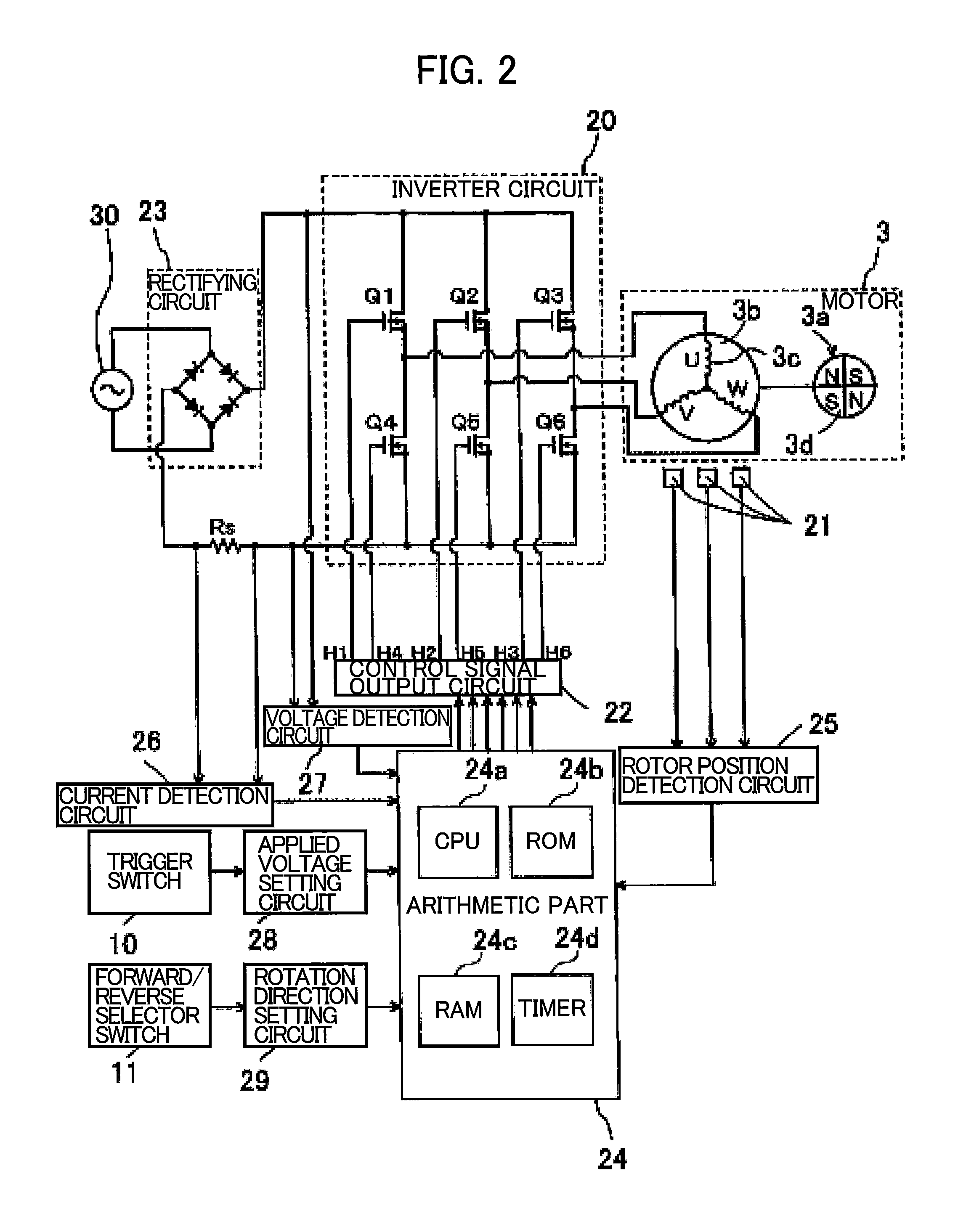
[0112]The following describes in detail the impact driver 1 according to a In the present embodiment, the impact driver 1 performs switching of the PWM duty D on the basis of the current value I input to the inverter circuit 20.

[0113]The arithmetic part 24 performs soft start control that gradually increases the PWM duty from an initial value to a target value when the motor 3 is started. FIG. 5 is a diagram for explaining the soft start control. As illustrated in FIG. 5, the arithmetic part 24 increases the PWM duty D from a predetermined initial value D0 to a target value at a certain increasing rate α (α>0). In the present embodiment, the target value of the PWM duty D is the first duty D1.

[0114]In the present embodiment, the ROM 24b of the arithmetic part 24 stores a current threshold value Ith corresponding to the power supply voltage effective value Ve. FIG. 6 is a diagram illustrating a relationship between the power supply voltage effective value and a current threshold val...

second embodiment

[0130]Next, the impact driver 1 will be described. In the present embodiment, the impact driver 1 performs switching of the PWM duty D on the basis of the voltage instantaneous value V to be input to the inverter circuit 20.

[0131]In the present embodiment, the ROM 24b of the arithmetic part 24 stores a voltage threshold value Vth corresponding to the power supply voltage effective value Ve. FIG. 11 is a diagram illustrating a relationship between the power supply voltage effective value and voltage threshold value in the impact driver according to the second embodiment. In the present embodiment, as illustrated in FIG. 11, the voltage threshold value Vth stored in the arithmetic part 24 assumes a fixed value of 140V when the power supply voltage effective value Ve falls between 100 V and 200 V. The arithmetic part 24 sets the voltage threshold value Vth according to the power supply voltage effective value Ve of the commercial AC power supply 30. Then, the arithmetic part 24 perfor...

third embodiment

[0147]Next, the impact driver will be described. In the present embodiment, the impact driver 1 performs switching of the PWM duty D on the basis of an elapsed time t from a zero-cross point to be described later.

[0148]In the present embodiment, the voltage detection circuit 27 also serves as a zero-cross detection unit of the present invention and detects a zero-cross point at which the voltage instantaneous value V to be input to the inverter circuit 20 becomes 0.

[0149]Further, in the present embodiment, the arithmetic part 24 also serves as a period detection unit of the present invention and measures a time between the two consecutive zero-cross points detected by the voltage detection circuit 27 by using a timer 24d to acquire a half period T0 of AC power output from the commercial AC power supply 30. Further, the arithmetic part 24 measures the elapsed time t from the zero-cross point by using the timer 24d.

[0150]The ROM 24b of the arithmetic part 24 stores a duty switching ...


PUM


Abstract

It is an object of the invention to provide a power tool capable of preventing damage of a switching element while maintaining drive power of a motor even when being connected to a power supply of different voltage. An impact driver 1 includes a motor 3; a rectifying circuit 23; an inverter circuit 20; and an arithmetic part 24. The rectifying circuit 23 is configured to rectify an input voltage from a commercial power supply 30. The inverter circuit 20 is configured to supply a rectified voltage output from the rectifying circuit 23 to the motor 3 as drive power. The arithmetic part 24 is configured to suppress occurrence of overcurrent where current flowing through the motor exceeds a predetermined current value.

Description

TECHNICAL FIELD[0001]The present invention relates to a power tool having a motor driven by a commercial AC power supply.BACKGROUND ART[0002]Conventionally, in a power tool used by being connected to a commercial AC power supply, AC power from the commercial AC power supply is rectified by a rectifying circuit and then smoothed by a smoothing capacitor. The resultant AC power is then supplied to an inverter circuit. The inverter circuit then outputs predetermined drive power and the predetermined drive power is input to a motor, whereby the motor is driven.[0003]In recent years, a small-sized power tool not provided with the smoothing capacitor is becoming popular. It is known that, in a power tool of this type, the current value flowing through the motor suddenly increases at a timing of the maximum amplitude of AC voltage.[0004]A voltage standard for the commercial AC power supply differs from countries to countries. Thus, for example, when a power tool of 100 V specification is c...

Claims


Application Information

Patent Timeline
IPC IPC(8): H02P6/00B25F5/00
CPCB25F5/00H02P6/002H02K7/145H02K11/33H02P6/28
Inventor KOIZUMI, TOSHIAKIIWATA, KAZUTAKA
Owner HITACHI KOKI CO LTD
Why Eureka
Try Eureka