Wireless Power Transmission System

a power transmission system and wireless technology, applied in the field of wireless transmission of power, can solve the problems of difficult or even impossible to provide a physical wire to the intended target, moving objects present a particularly difficult problem in transmitting energy, detection, reception and transmission equipment must also be very larg

Inactive Publication Date: 2006-11-30
BALDIS SISINIO F +2
View PDF16 Cites 349 Cited by
  • Summary
  • Abstract
  • Description
  • Claims
  • Application Information

AI Technical Summary

Benefits of technology

[0011] An embodiment of the transmitter described herein uses a low power electromagnetic beam to locate the receiver. While locating the receiver, the transmitter scans an area for the receiver using the low power beam. To overcome the issues described above regarding accurately locating the transmitter, the transmitter employs adaptive optical focusing and multistage scanning. In an embodiment, an optical focusing component will be used in conjunction with the multistage beam scanner allowing for micro adjustment of the beam placement. A coarse beam will initially scan the area until the receiver is located. Because the initial beam is coarse, the area can be rapidly scanned. Location is confirmed by passive optical feedback from the receiver. After the initial location is made, the transmitter focuses the beam, and through optics, can micro-adjust the beam position for additional accuracy and placement on the target area of the receiver. Once the receiver is located, optical focusing will be used to focus the beam for maximum power transmission, and the beam source may be switched into high power transmission. Optionally, if at any time the transmitter's beam detector ceases to detect the reflected beam (i.e., the optical feedback) or if the intensity distribution seen at the position sensor is not as expected, it shuts down the high power beam. This tightly coupled feedback loop enhances safety and is an improvement over the prior art which employs a separate channel for feedback and beam shutdown.
[0013] By analyzing these characteristics, the transmitter can micro-adjust the beam position until the desired reflected characteristics are attained, which would correspond to the optimal position of the beam on the receiver. Once the transmitter determines the position of the receiver, the transmitter optionally tracks the location of the receiver to ensure that the beam is optimally positioned on the receiver during any subsequent movement of the receiver or the transmitter. The tracking function takes frequent measurements of the receiver's location and makes micro-adjustments to the beam location to keep it within the tight limits needed for optimal power transmission. By constantly tracking the receiver, the transmitter need not relocate the receiver every time it is moved, and may instead, transmit power continuously with the power beam adjusted according to the tracking function. Optional predictive software tracking algorithms may be used to more accurately track the receiver.
[0014] In another embodiment, the transmitter includes a safety feature to prevent unintended damage to property or people. In operation, the transmitter receives a portion of the beam back from the receiver and uses the reflected beam to determine and track the receiver's location. If, however, an object obstructs the beam the transmitter would detect this instantaneously because the reflected beam would necessarily also be obstructed. In such a circumstance, the transmission of power is turned off so that the beam will not cause damage to the obstructing object. This closely coupled system ensures that the beam will never be in high power mode when the reflected beam is not seen at the transmitter. This is an improvement over the prior art because beam obstruction can be detected without the need of complicated circuitry and / or another channel of communication.
[0016] In another embodiment, the transmitter optionally comprises a modulator and demodulator, and the receiver comprises a modulator and demodulator. This embodiment allows for two way communication of data between the receiver and transmitter. And because the data is encoded on the beam and because the beam optically connects only the transmitter and receiver, the 2 way communication is secure from eavesdropping.

Problems solved by technology

Wireless power transmission is generally used in situations where providing a physical wire to the intended target is difficult or even impossible.
For example, moving objects present a particularly difficult problem in transmitting energy.
Because microwaves are very long waves, the detection, reception and transmission equipment must also be very large.
This limits its application and drives up costs.
It is beneficial because the energy transmission need not be in line of sight; however, it can travel through objects and cause damage to unintended (and unseen) targets.
The main drawback here, however, is that the magnetic field is generally emitted radially, meaning that the amount of power received drops off as a function of the square of the inverse of the distance from the transmitter (i.e., 1 / r2).
So magnetic induction power transmission is only possible over very short distances and much of the energy transmitted is wasted.
Having a focused light power beam introduces a new set of problems, however: (1) the power beam must be precisely focused on a target over very long distances and (2) because the power beam is high in energy, it must be maintained on the target, lest it diverges and causes unintended damage.
People may be especially susceptible to a high intensity power beam, and U.S. Pat. No. 4,08,747 does not present an effective method to safely use the high intensity beam.
So if the receiver loses its power, then energy transmission is impossible.
Also, if the new channel of communication fails, either through equipment malfunction or interference, then effective energy transmission is again impossible.
Finally, the '057 application does not address how to accurately find and position the beam on the receiver, and how to maintain that position on the receiver.

Method used


Image

  • Wireless Power Transmission System
  • Wireless Power Transmission System
  • Wireless Power Transmission System

Examples


Embodiment Construction

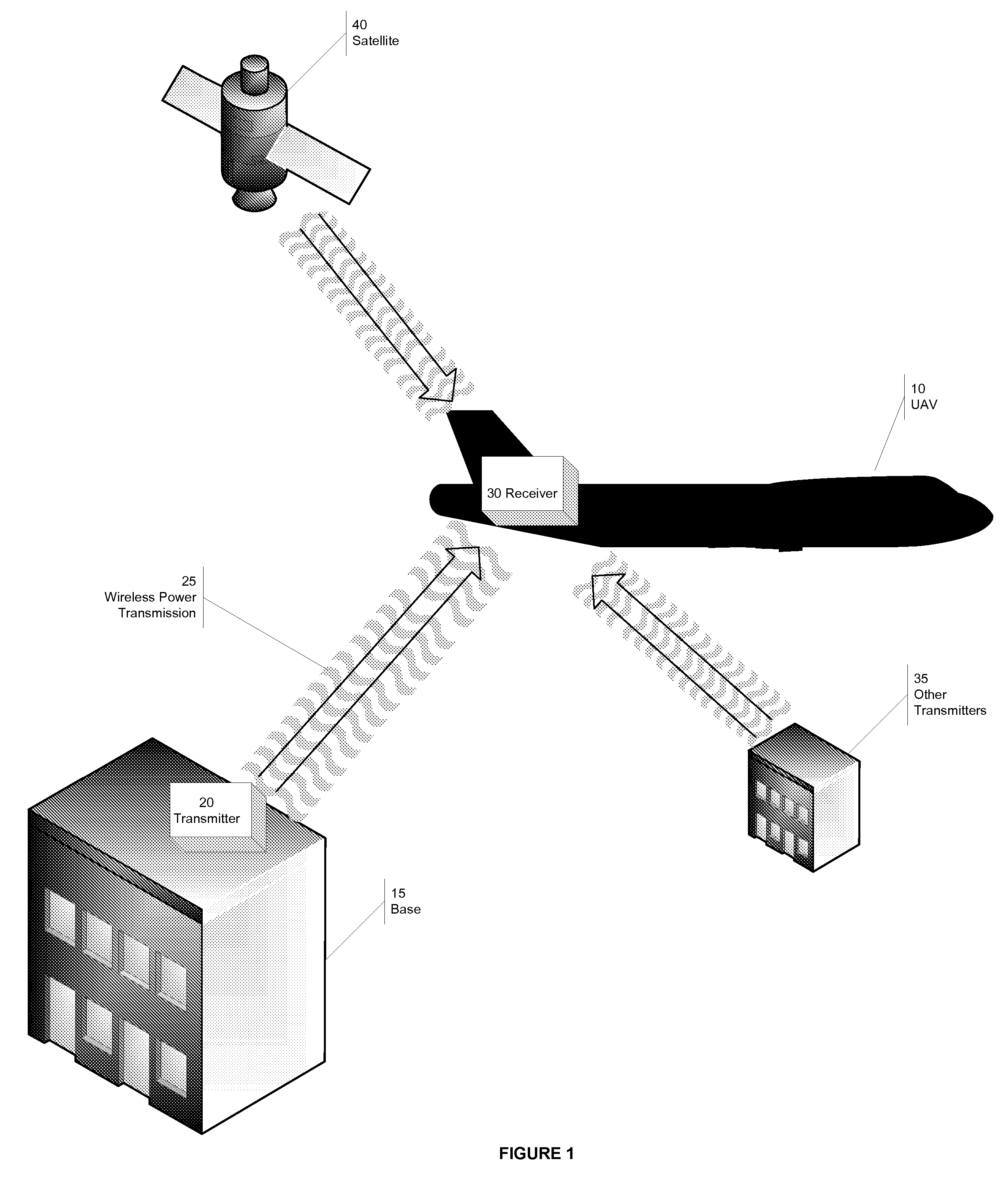
[0030] What is described below is a novel wireless energy transmitter and receiver for wireless energy and data transmission over large distances. FIG. 1 shows one example of an application of the technology described herein. An unmanned air vehicle (UAV) 10 requires significant power and, in its optimal operation, should be in the air as much as possible. Unfortunately, because UAVs 10 consume power quickly, their flying time, and consequently their range, is limited. The power transmission methods and devices described herein can be used to transmit energy efficiently and effectively to the UAV 10, dramatically increasing the UAV's range and flying time. Specifically, the base 15 contains a transmitter 20 that transmits wireless power 25 to a receiver 30 located on the UAV 10, allowing the vehicle to have a much longer surveillance runs. Other strategically positioned power transmitters 35 could be placed near the UAV's 10 surveillance area to further increase the UAV's 10 range a...


PUM

PropertyMeasurementUnit
reflectanceaaaaaaaaaa
distanceaaaaaaaaaa

Abstract

A novel method for wireless power transmission that comprises a transmitter and a receiver is disclosed. The receiver does not require an independent power source and is comprised of an optical feedback to the transmitter, and therefore does not require a separate communication channel to the transmitter. The transmitter uses the optical feedback to locate and track the receiver. The transmitter can optionally employ a macro adjusters and micro adjusters that direct the beam onto the receiver for optimal power transmission. The system also optionally has a tight loop beam detector to enhance safety of the system. Either the receiver and / or the transmitter may also encode data on the energy transmission, resulting in one-way or two-way data transmission.

Description

1 CLAIM OF PRIORITY [0001] The present patent application claims priority to U.S. provisional patent application 60 / 684,203 filed on May 23, 2005 by inventors Sisinio F. Baldis, Hector A. Baldis, and Jessica J. Baldis. The content of the provisional patent application is incorporated herein by reference.2 FIELD OF THE INVENTION [0002] The present invention relates to the wireless transmission of power. 3 BACKGROUND OF THE INVENTION [0003] Wireless power transmission is generally used in situations where providing a physical wire to the intended target is difficult or even impossible. For example, moving objects present a particularly difficult problem in transmitting energy. In the past, moving objects like trains, used heavy infrastructure (including overhead power cables) to supply the needed energy. Therefore, there exists a need for efficient and safe wireless power transmission that avoids costly infrastructure. [0004] Recently, there has been much experimentation with microwav...

Claims


Application Information

Patent Timeline
Patent Type & Authority Applications(United States)
IPC IPC(8): C12Q1/68H01J40/00
CPCH01Q1/248H01Q15/148H01Q3/46
Inventor BALDIS, SISINIO F.BALDIS, HECTOR A.BALDIS, JESSICA J.
Owner BALDIS SISINIO F
Why Eureka
Try Eureka