[0008]It is now an object of the present invention to specify a method and a microscope of the type mentioned at the beginning which enable rapid scanning of a sample with structurally simple and cost effective means in conjunction with a compact design.
[0012]The method according to the invention and the microscope according to the invention can be used in a particularly advantageous way in conjunction with first and second states that are very
long lasting or are even temporally stable permanently. In this case, it is possible to select for the saturation of the transition from the first into the second state a comparatively long period within which the energy of the optical
signal that is required for saturation is irradiated. The local intensities relating to transitional saturation can thereby be selected to be very slight. Above all, the
total energy available from a
radiation source of the optical signal can be distributed over voluminous regions in the
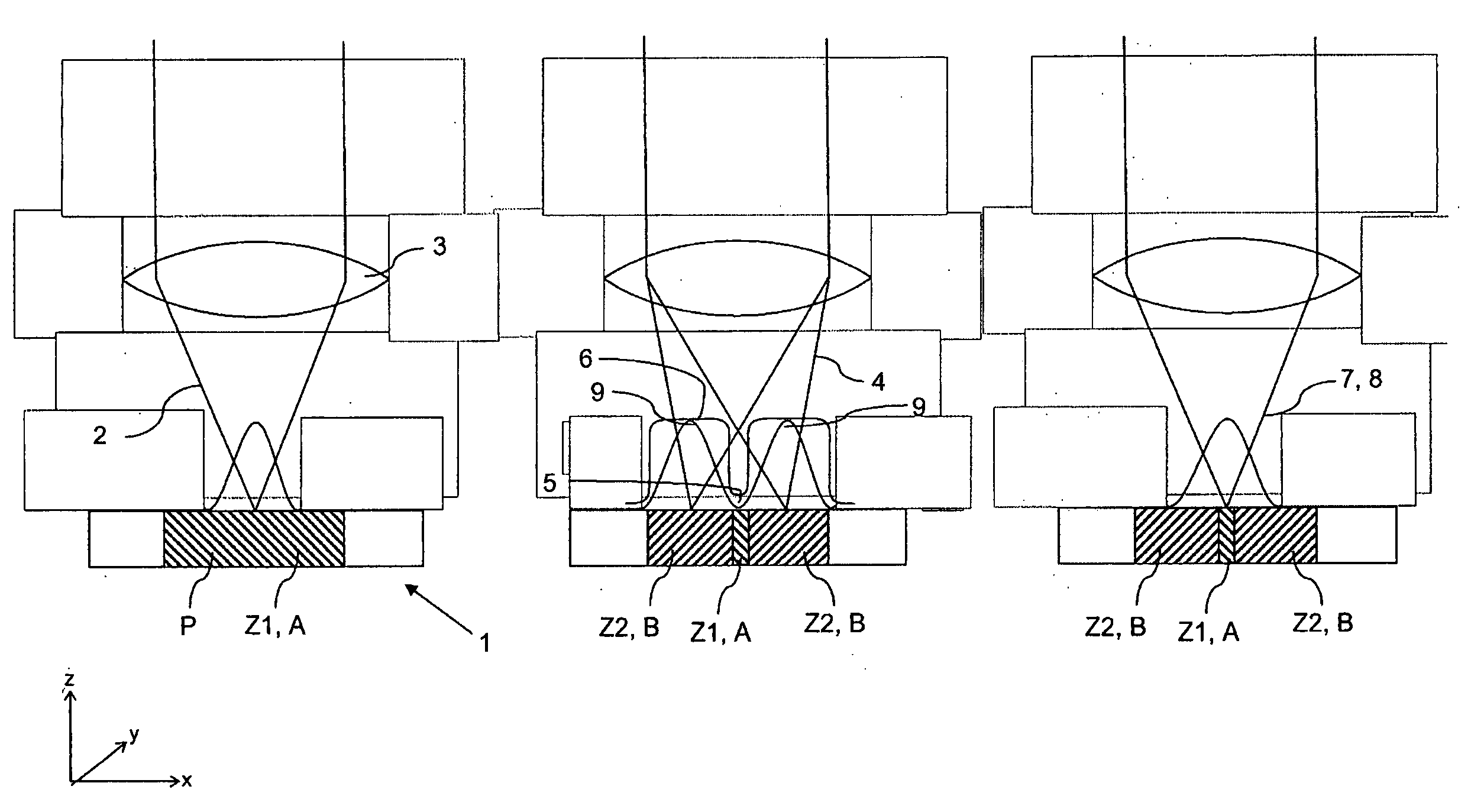
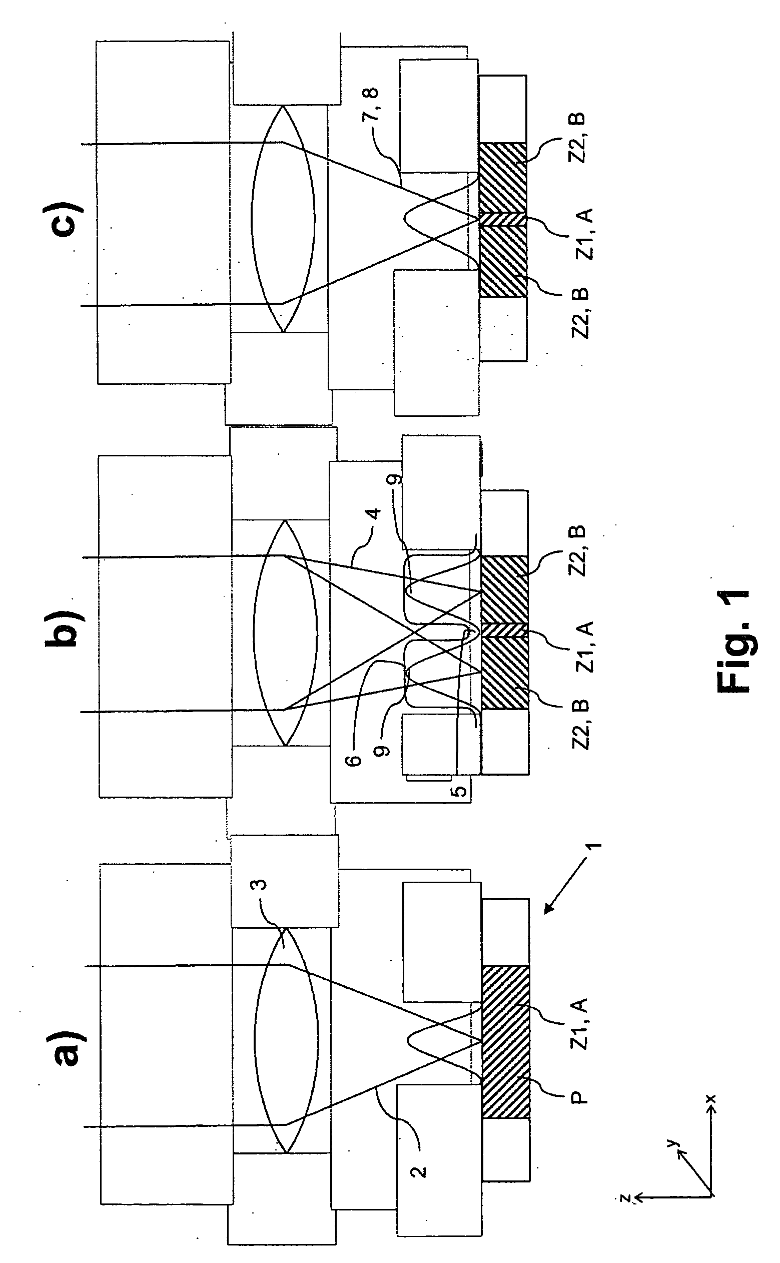
sample space, and a number of intensity zero points, or an extended zero point can be produced. The saturation can be achieved despite the low local intensities resulting therefrom in the vicinity of the zero point(s) by comparison with the application of the total signal around only one punctiform zero point. This requires that the signal be irradiated only for a sufficiently long time until all the molecules in the surroundings of the zero points are finally in the second state. This is a decisive difference from the case of a shortlived state (for example in the STED method with a typical lifetime of ˜1 ns for a
fluorescence-capable state A), where the energy required for saturation must be irradiated in such a short time (substantially faster than the rate A→B) that the total power of the
radiation source is sufficient only to produce one (or at most a few) local zero points. It may be demonstrated for concrete systems that it is possible in the case of stable states (for example photochromic dyes) or long lived states (for example transfer into the triplet
system in the case of the GSD, GSD=
Ground State Depletion, method) for the power of cost effective and commercial
laser systems to be distributed over such large regions that a number of punctiform intensity zero points (>>10) or entire stripes of vanishing intensity, in the immediate vicinity of which saturation can be achieved as before, can be produced in the sample. This enables a parallelized imaging when the sample is simultaneously scanned with the multiplicity of punctiform zero points or with zero point lines, and the signals are detected simultaneously for each zero point in a separate fashion by a
detector. In this way, it is possible to design microscopes with resolutions below the classic
diffraction limit, their imaging rate being in the region of STED-based methods, and being substantially increased by comparison with systems with a single local zero point.
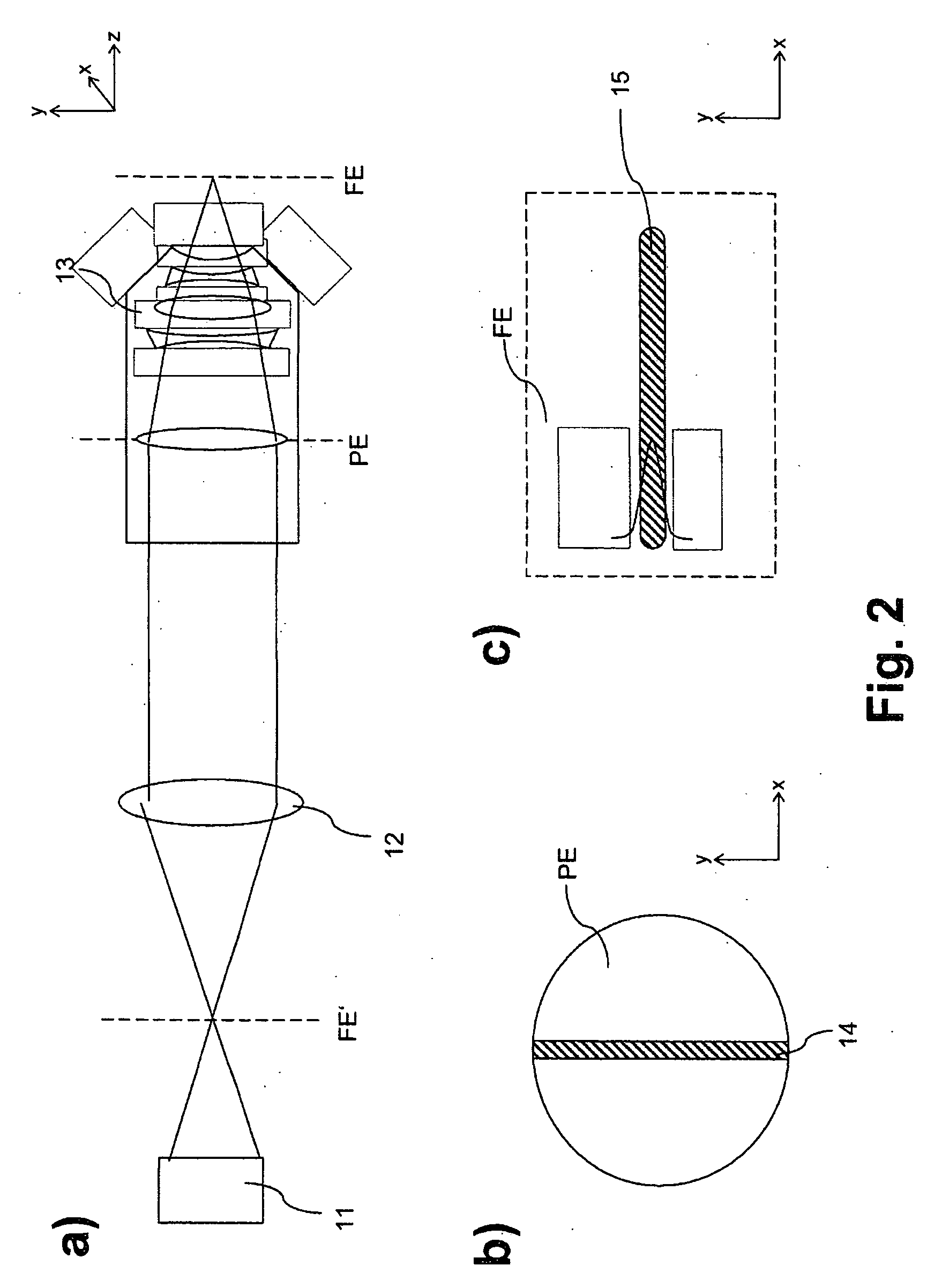
[0018]With regard to a particularly compact design, the optical component for producing the
pupil line, and the phase modulating element could be arranged as a
structural unit in the illuminating beam path. With regard to a high degree of flexibility, the optical component for producing the
pupil line, and the phase modulating element could also, however, be arranged as separate units at different positions in the illuminating beam path.
[0020]In a particularly advantageous way, the light of the optical signal is polarized perpendicular to the
pupil line in order in this way to exclude
depolarization effects to a maximum extent.
[0023]It is provided in a further preferred design that the optical signal and a test signal are respectively generated in order to read out the first state by means of pulsed light sources. A synchronization of the pulsed light sources proves to be advantageous in this case.

