Controlling and staggering operations to limit current spikes

a technology of current spikes and operations, applied in the direction of power supply for data processing, digital storage, instruments, etc., can solve problems such as current consumption profiles of flash dies

Inactive Publication Date: 2014-04-24
APPLE INC
View PDF5 Cites 23 Cited by
  • Summary
  • Abstract
  • Description
  • Claims
  • Application Information

AI Technical Summary

Benefits of technology

[0008]The controller (e.g., the host processor and / or the flash controller) may be configured to manage the peak power consumption of the system. For example, the controller may limit the number of subsystems that can perform power-intensive operations at the same time or aid a subsystem in determining the peak power the subsystem may consume at any given time. This way, the total power of the system may be maintained within a threshold level suitable for operation of the hosting system.

Problems solved by technology

In such flash systems, the subsystems may include different flash dies, which may perform power-intensive operations that cause spikes in the flash die current consumption profile.

Method used


Image

  • Controlling and staggering operations to limit current spikes
  • Controlling and staggering operations to limit current spikes
  • Controlling and staggering operations to limit current spikes

Examples


Embodiment Construction

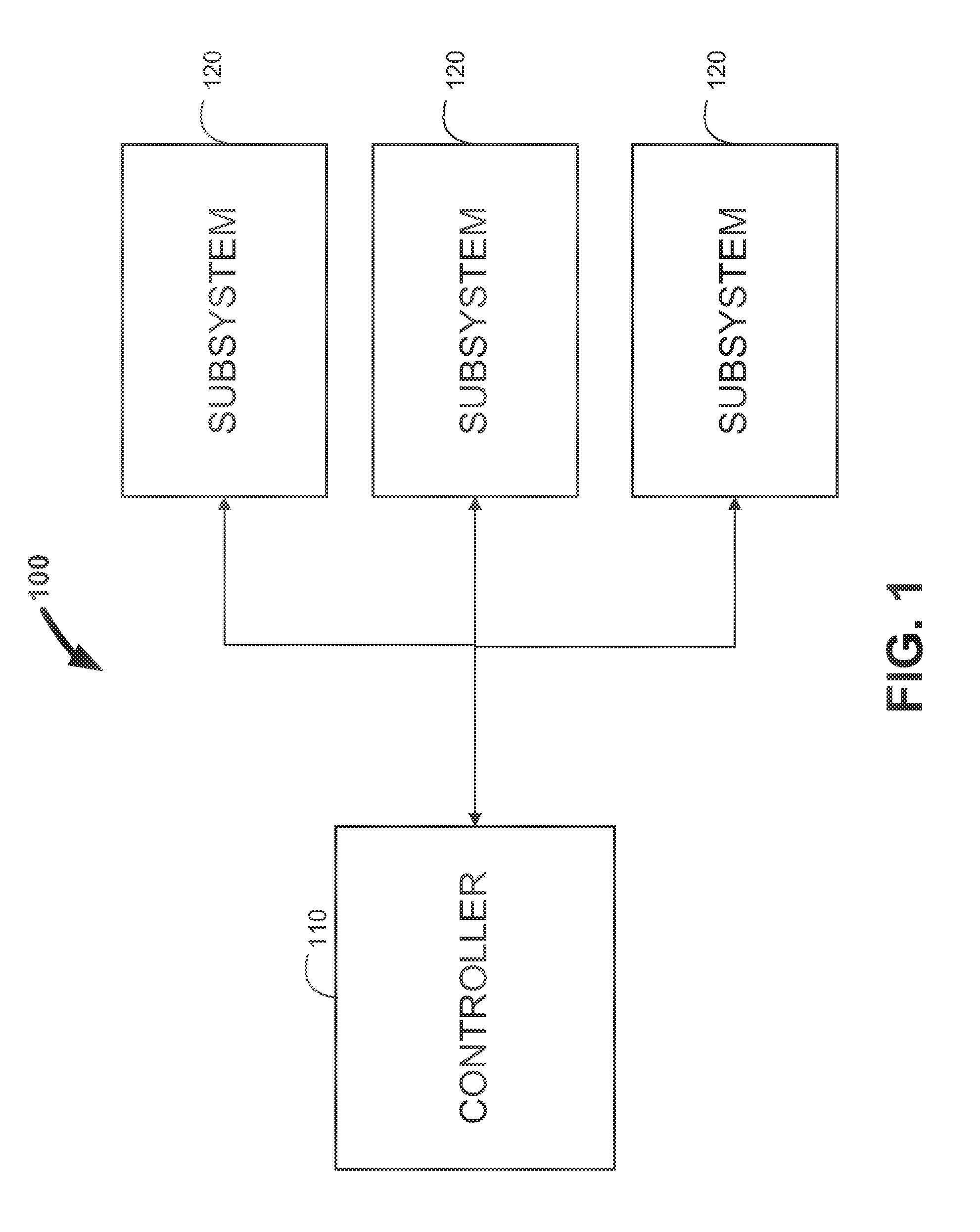
[0018]FIG. 1 is a schematic view of illustrative system 100 that may suffer from peak power issues. In particular, system 100 can include controller 110 and multiple subsystems 120, where the combined power consumption of subsystems 120 may be undesirably peaky when not suitably managed by controller 110. In some embodiments, each of subsystems 120 may have substantially the same features and functionalities. For example, subsystems 120 may have been manufactured using substantially the same manufacturing process or may have substantially the same specifications (e.g., in terms of materials used, etc.).

[0019]Each of subsystems 120 may have a current or power profile that is peaky. In particular, during operation, each of subsystems 120 may perform some operations that are higher in power and some operations that are lower in power. Thus, over time, the current or power profile of each of subsystems 120 may rise and fall, where the highest peaks occur when a subsystem is performing i...


PUM


Abstract

Systems and methods are disclosed for managing the peak power consumption of a system, such as a non-volatile memory system (e.g., flash memory system). The system can include multiple subsystems and a controller for controlling the subsystems. Each subsystem may have a current profile that is peaky. Thus, the controller may control the peak power of the system by, for example, limiting the number of subsystems that can perform power-intensive operations at the same time or by aiding a subsystem in determining the peak power that the subsystem may consume at any given time.

Description

CROSS-REFERENCE TO RELATED APPLICATIONS[0001]This application claims the benefit of U.S. Provisional Patent Application No. 61 / 294,060, filed on Jan. 11, 2010, which is hereby incorporated by reference herein in its entirety.FIELD OF THE INVENTION[0002]This can relate to managing the peak power consumption of a system, such as a NAND flash memory system.BACKGROUND OF THE DISCLOSURE[0003]Electronic systems are becoming more and more complex and are incorporating more and more components. As such, peak power issues for these systems continue to be a concern. In particular, because many of the components in a system may operate at the same time, the system can suffer from power or current spikes. This effect may be particularly pronounced when the system components are each performing high-power operations.[0004]A flash memory system, which is commonly used for mass storage in consumer electronics, is one example of a current system in which peak power issues are a concern.SUMMARY OF T...

Claims


Application Information

Patent Timeline
Patent Type & Authority Applications(United States)
IPC IPC(8): G11C16/30
CPCG11C16/30G06F1/26G06F1/3203G11C16/06
Inventor WAKRAT, NIR J.POST, DANIEL J.HERMAN, KENNETH L.KHMELNITSKY, VADIMSEROFF, NICHOLAS C.THIO, HSIAO H.BYOM, MATTHEW J.
Owner APPLE INC
Why Eureka
Try Eureka