Radio communication system

a radio communication and system technology, applied in the field of radio communication systems, can solve the problems of complex constitution of optical transmitters such as the optical/electric converter and the electric/optical converter, the complexity of the apparatus, and the large size of the apparatus, so as to simplify and miniaturize the constitution of the control station and the base station, and reduce the number of optical fibers

Inactive Publication Date: 2006-05-09
KK TOSHIBA
View PDF19 Cites 608 Cited by
  • Summary
  • Abstract
  • Description
  • Claims
  • Application Information

AI Technical Summary

Benefits of technology

[0039]According to the present invention, each of a transmitter and a receiver can transmit a signal by one piece of the optical fiber, respectively. Because of this, only one pair of an electric / optical converter and a optical / electric converter is necessary to each of the transmitter and the receiver without depending on the number of the antenna elements. Accordingly, the following advantageous effects are obtained.
[0040]First, it is possible to reduce the number of the optical fiber more than that of a conventional fiber multiple system. Furthermore, the optical transmitter of the present invention does not need an optical multiplexer unit and an optical demultiplexer, different from the wave length multiple system, and the electric / optical converter does not need a wave length control circuit. It is possible to reduce a constitution of the optical transmission parts more than the radio communication system using the conventional fiber multiplex and wavelength division multiplex systems because the system on the present invention requires one pair of the electric / optical converter and the optical / electric converter, simplifies and miniaturizes constitutions of the control station and the base station to a large degree. It is possible to reduce cost of the base station by reducing the number of optical transmission components that cost is higher than electrical components.
[0041]Furthermore, according to the present invention, applying phase-locked loop techniques or transmission of said sub-carrier multiplexing signal with local oscillator signals to the above-mentioned radio communication systems, it is possible to maintain in principle relative phase difference of the transmitted / received signal of the antenna element provided with the base station, even if the effective length changes by the peripheral temperature's change. Therefore, it is possible to estimate arrival direction of the received signal in the beam calculation circuit of the control station side. It is possible to control beam pattern forming of the array antenna of the base station side. That is, it is unnecessary to dispose the beam calculation circuit and the control circuit on the base station side. It is possible to constitute of passive components and to miniaturize the overall constitution. Even when a large number of base stations provided with these advantages are arranged in a broad area, a highly reliable and highly stable radio communication system can be provided.
[0042]In the above-mentioned radio communication system according to the present invention, there is a system of applying a beam forming network and level detecting means. The radio communication system of applying such a system comprising:
[0043]a base station provided with a variable directional array antenna whose directivity changes by an electric signal for supplying power to a plurality of antenna elements; and
[0044]a control station provided with a signal calculation circuit for performing weighting of electric signal applied to said plurality of antenna elements,

Problems solved by technology

Therefore, elements constituting optical transmitters of the base station and the control station largely increase, the constitution is complicated and an apparatus becomes large-sized.
On the other hand, if the optical fiber is provided by each antenna element, the number of optical fibers for connecting the base station to the control station largely increases, and accordingly the constitutions of optical transmitters such as the optical / electric converter and the electric / optical converter become complicated and large-sized.
Thus, in the conventional radio communication system, provided with the adaptive antenna, for utilizing the ROF technique to perform the signal transmission, since there are many constituting elements for the optical transmitter, the constitution is complicated, it is difficult to miniaturize the base station and control station, and cost cannot be reduced.

Method used


Image

  • Radio communication system
  • Radio communication system
  • Radio communication system

Examples


second embodiment

[0175]In a second embodiment, a reference signal outputted from the base station local oscillator 6 and a reference signal outputted from the control station local oscillator 13 are shared.

[0176]FIG. 8 is a block diagram of the second embodiment of the radio communication system according to the present invention. In FIG. 8, constituting parts common to FIG. 3 are denoted by the same reference numerals, and respects different from FIG. 3 will mainly be described hereinafter.

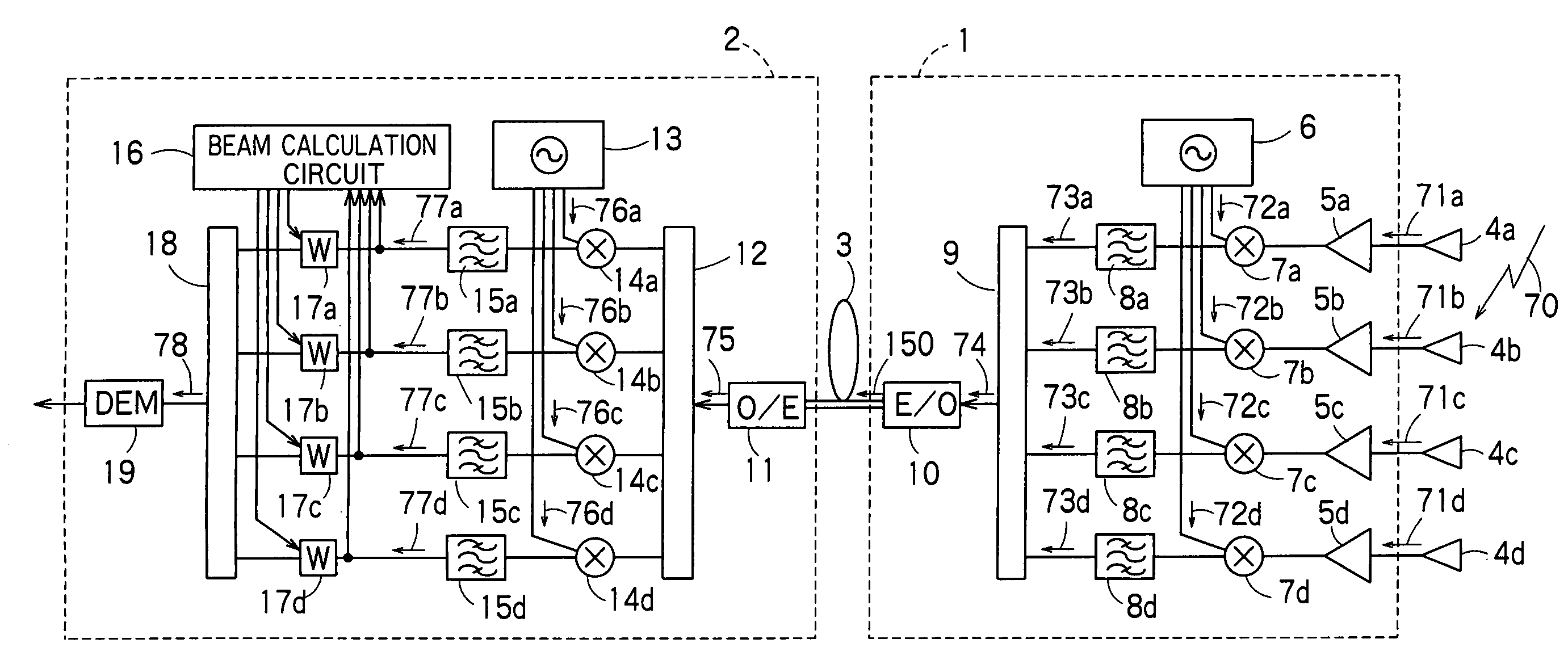
[0177]In the radio communication system of FIG. 8, the constitution of a receiver to the control station 2 from the base station 1 is similar to that of the first embodiment except the constitutions of the base station local oscillator 6 and control station local oscillator 13.

[0178]The radio communication system of FIG. 8 is characterized in that the constitution of the transmitter to the base station 1 from the control station 2 is newly added, and the base station local oscillator 6 and control station local o...

third embodiment

[0212]For the transmitter of the second embodiment, in order to minimize and simplify the constitution of the base station 1, the transmission weighting circuits (second weighting means) 43a to 43d are disposed on the control station 2 side. The transmitted signals 87a to 87d transmitted to the base station 1 side from the control station 2 side differ only in phase and amplitude, different from the received signals 71a to 71d propagated in the radio propagation line of the receiver and influenced by noise, phasing, and the like. Therefore, the constitutions of the weighting circuits 43a to 43d can be simplified.

[0213]On the other hand, when the weighting circuits 43a to 43d can be disposed on the base station 1 side, the intermediate frequency signal 85 and the weighting control signal from the beam calculation circuit 16 may be transmitted to the base station 1 side from the control station 2 side, and weighted on the base station 1 side to generate the transmitted signal.

[0214]In...

fourth embodiment

[0227]In a fourth embodiment, instead of performing the optical transmission by subjecting the transmitted signals from the respective antenna elements or the received signals of the respective antenna elements to sub-carrier wave multiplexing, the signal transmission is performed by a spread spectrum multiplex system.

[0228]FIG. 13 is a block diagram showing a constitution of the fourth embodiment of the radio communication system according to the present invention. In FIG. 13, constituting parts common to the first to third embodiments are denoted by the same reference numerals.

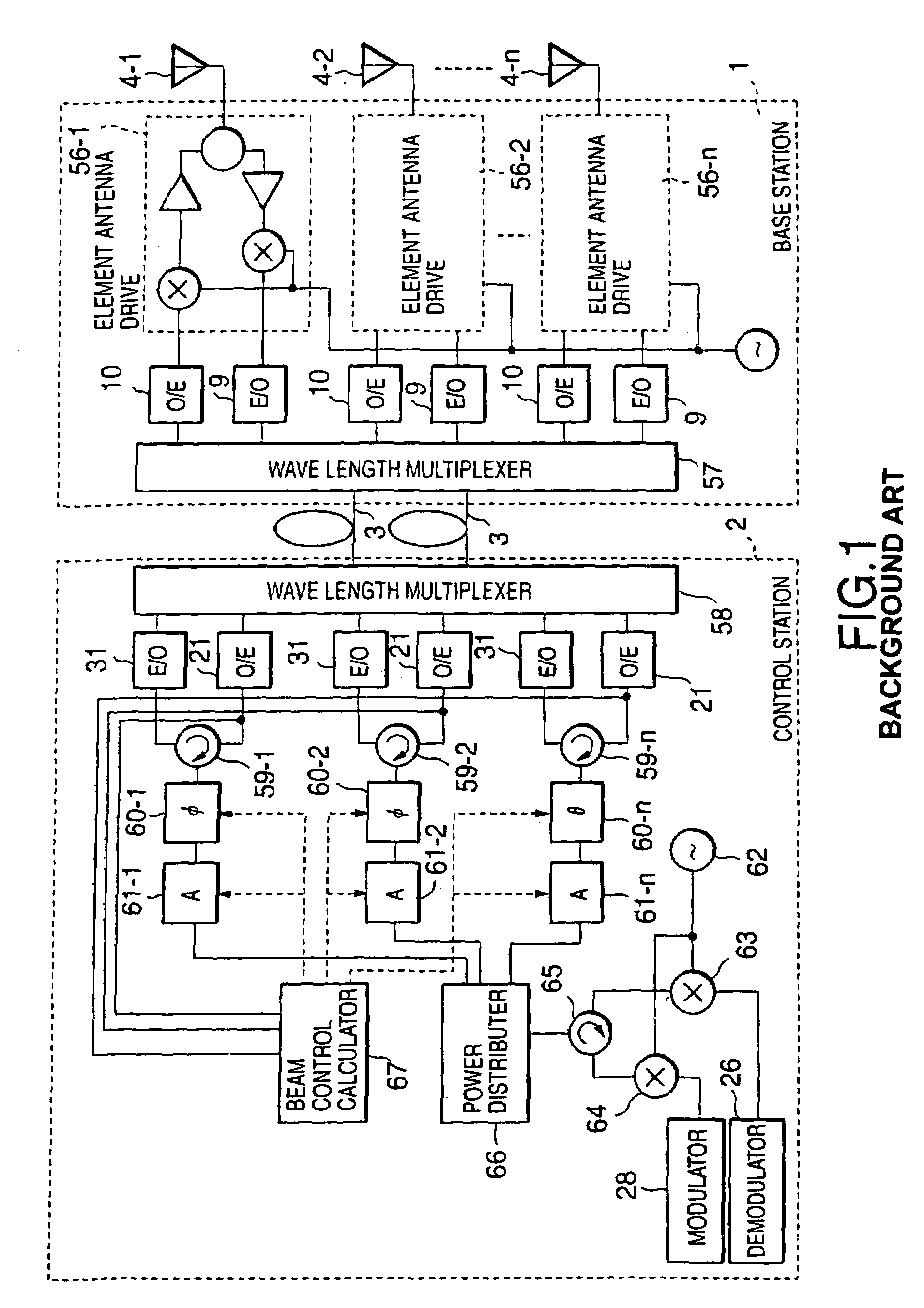
[0229]The base station 1 of FIG. 13 is constituted by newly adding, to the base station 1 of FIG. 1, spread spectrum units (first spread spectrum multiple signal generation means) 56a to 56d for performing spread spectrum for the received signals 71a to 71d received at the antenna elements 4a to 4d.

[0230]Moreover, the control station 2 of FIG. 13 is provided with de-spread spectrum units (reverse diffusion ...


PUM


Abstract

There is disclosed a radio communication system in which a constitution of a base station and further a control station can be simplified. A radio communication system according to the present invention converts a received signal received by a plurality of antenna elements in a base station to a signal of different frequency band, and then conflates the converted signal in order to generate sub-carrier wave multiplex signal. The signal is converted to an optical signal, and then the optical signal is transmitted to a control station via an optical fiber. Or the control station performs weighting to phase of the transmitted signal transmitted from a plurality of antennas of a base station, and then performs frequency conversion to different frequency band, and then conflates the converted signal in order to generate the sub-carrier wave multiplex signal. The signal is converted to an optical signal, and then an optical signal is transmitted to the base station side via the optical fiber. The control station and the base station divides the received sub-carrier wave multiplex signal by each frequency band, and then the frequency of the divided signals are converted to the same frequency band in order to generate the transmitted / received signal of each antenna element. By such a constitution, it is possible to reduce constituent of the optical transmission components to the minimum and to simplify the constitution of the base station. Furthermore, it is possible to maintain the relative phase difference and the relative intensity of the transmitted / received signal of each antenna element. Because of this, it is possible to estimate an arrival direction of the received signal and to control radiation beam pattern of the transmitted signal.

Description

BACKGROUND OF THE INVENTION[0001]1. Field of the Invention[0002]The present invention relates to a radio communication system which is constituted of a base station equipped with a variable beam-pattern array antenna such as an adaptive array antenna, and a control station connected to the base station via an optical fiber and which is provided with a function of controlling the variable beam-pattern array antenna on the side of the control station.[0003]2. Related Background Art[0004]Much attention has been paid to a radio on fiber (ROF) technique of connecting a base station and a control station for mobile communication represented by cellular phones and intelligent transport systems (ITS) to each other by an optical fiber in order to perform signal transmission. According to the ROF technique, a radio signal is transmitted from the base station to the control station via an optical fiber, and a modulator / demodulator, a controller and the like are collectively contained in the co...

Claims


Application Information

Patent Timeline
Patent Type & Authority Patents(United States)
IPC IPC(8): H04M1/00H04B7/26H01Q3/26H04B7/06H04B7/08H04B10/2575H04J14/02H04W88/08
CPCH01Q3/2605H01Q3/2676H04B7/0617H04B7/086H04W88/08H04B10/25753H04B17/20H04J14/02H04J14/0298H04B17/10H04B7/26
Inventor SETO, ICHIROMURAKAMI, YASUSHISHIBATA, OSAMUMATSUOKA, HIDEHIRO
Owner KK TOSHIBA
Why Eureka
Try Eureka