
Method and apparatus for monitoring and communicating with an implanted medical device

a medical device and communication method technology, applied in the field of communication systems, can solve the problems of short communication interface, high cost, and patient trauma, and achieve the effects of facilitating reprogramming, monitoring and recharging, and simplifying surgery

Inactive Publication Date: 2005-10-18
BRAEMAR MFG
View PDF134 Cites 620 Cited by
  • Summary
  • Abstract
  • Description
  • Claims
  • Application Information

AI Technical Summary

Benefits of technology

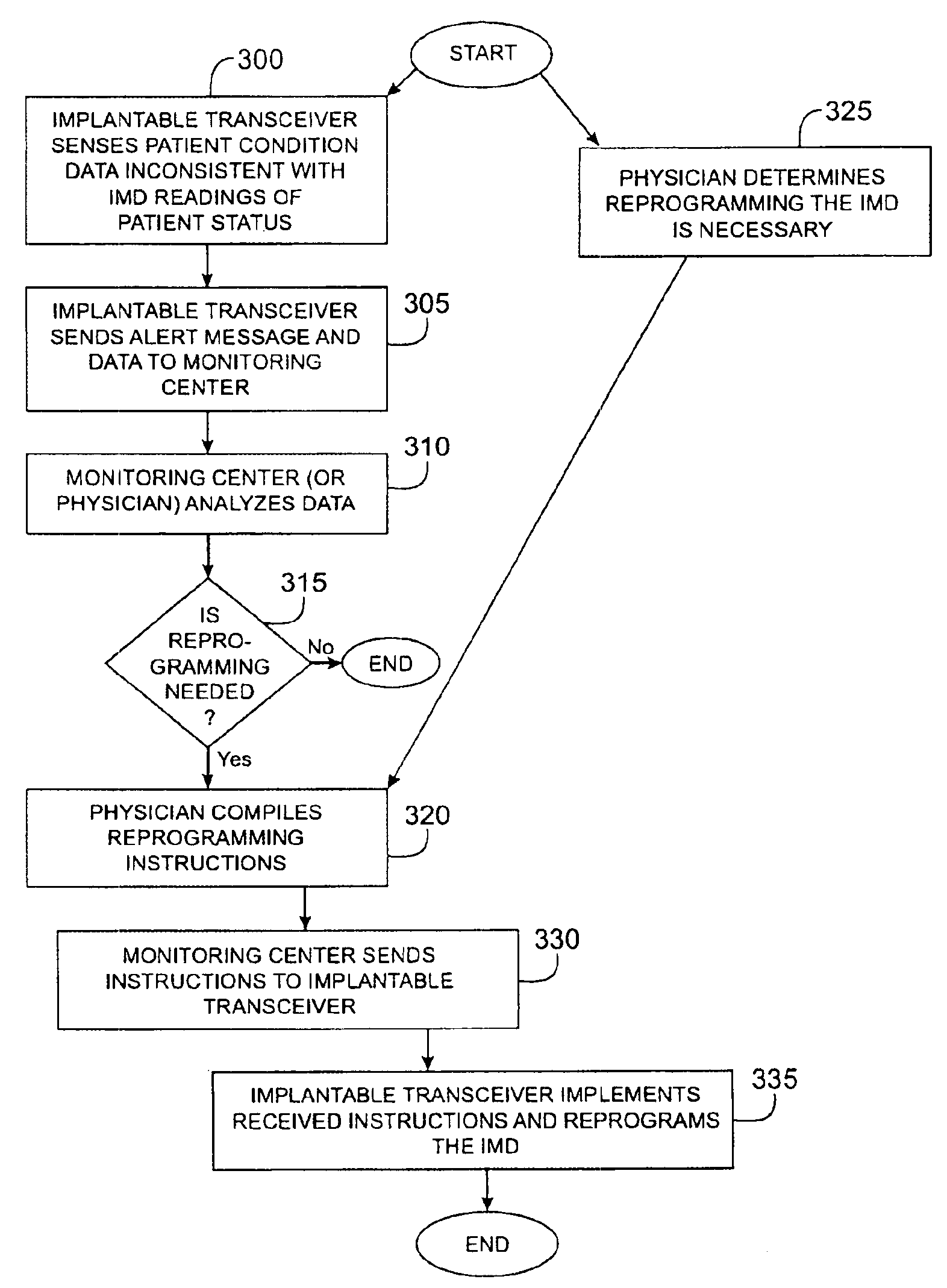
[0016]One advantage of the invention is that the transceiver is capable of automatically sending an alert message to the monitoring center, and ultimately a physician, if the physiological signals from the patients body indicate the patient is in need of immediate medical attention. In this way the invention fulfills the need of automatic physician notification without patient-initiated communication.
[0017]Another advantage of the invention is, with the transceiver apparatus electrically isolated from the IMD, a physician can simply implant a transceiver apparatus into a patient with an already-implanted IMD, rather than replace the existing IMD with a new IMD incorporating an integrated transceiver. In this way, surgery is simplified and the impact of the surgery on the patient is minimized.
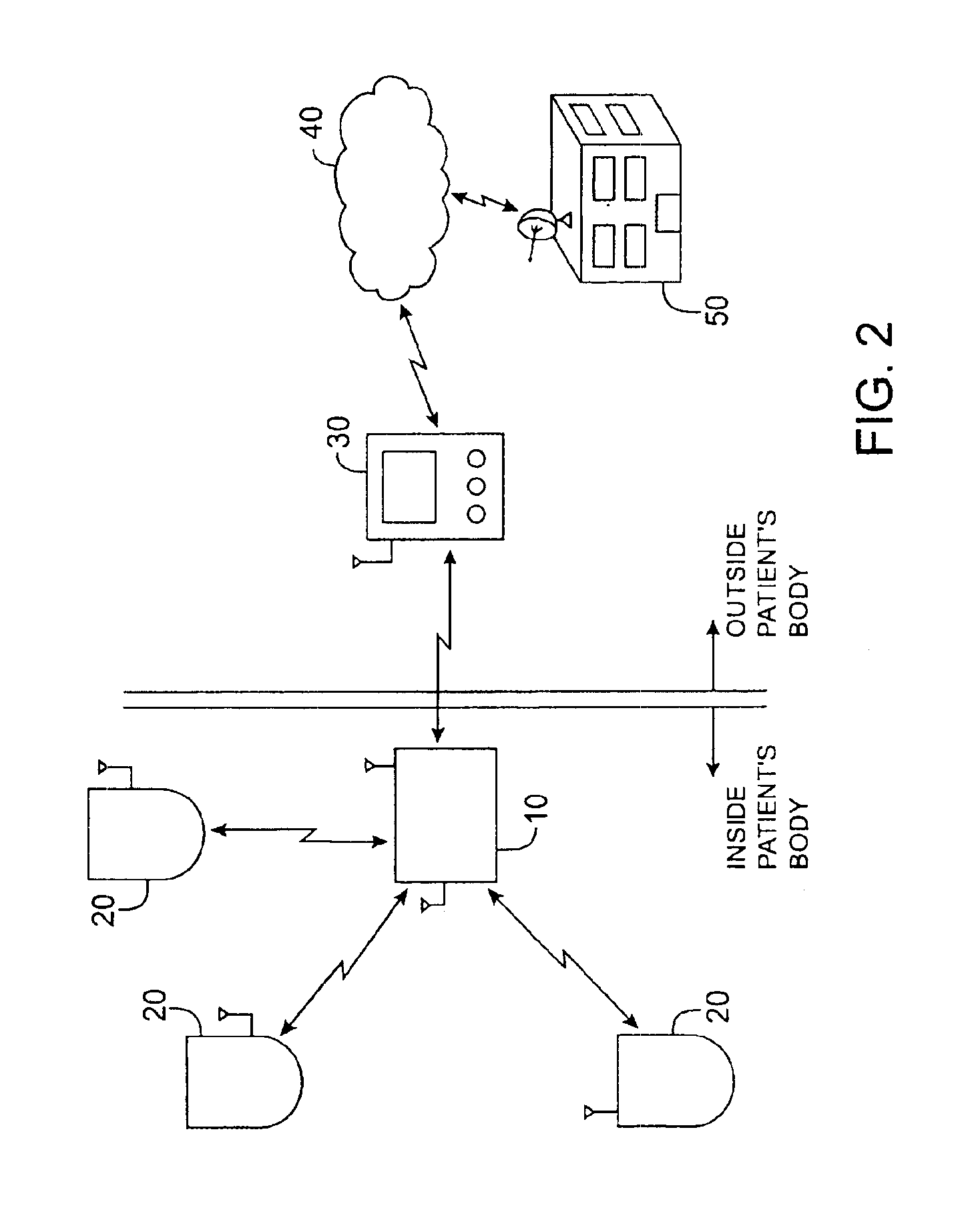
[0018]An additional advantage of the invention is that the transceiver apparatus is capable of monitoring and communicating with more than one IMD. Thus, a patient with multiple IMDs could have a single transceiver implanted that will facilitate the reprogramming, monitoring, and recharging of each individual IMD. This reduces the number of devices implanted into a patient as well as the size and complexity of the IMDs. The invention also eliminates any need to electrically connect an already-implanted transceiver with a soon-to-be-implanted IMD, thereby reducing the time and physical impact of surgery. In addition, companies that design IMDs can design all new IMDs to be compatible with a standard and separate transceiver. Thus, with standardized technology, the cost to patients is decreased and IMD options are increased with increased compatibility.
[0019]In one embodiment, the implantable transceiver operates in various modes. In one mode the implantable transceiver monitors the operation of the IMD and detects situations in which the IMD is not functioning properly. In the event an IMD is not functioning properly, the implantable transceiver reprograms the IMD according to reprogramming instruction received from the monitoring center or already recorded in the memory of the implantable transceiver. In another mode, the implantable transceiver monitors the patient's physical condition and automatically notifies a physician when an emergency condition is detected.

Problems solved by technology

Unfortunately, such communication interfaces are very short-range due to the limited size and power allowances of the IMD.
Additionally, in most cases today, recharging of the IMD device is an invasive procedure which creates trauma for the patient.
Due to the short-range communication limitation, activities such as monitoring, maintenance, and programming of an IMD must be performed using equipment in close proximity to the IMD.
It is cumbersome, time-consuming, and costly for patients to visit a physician's office to have an IMD reprogrammed.
It is also cumbersome and costly to conduct and / or schedule transtelephonic pacer checks, which require application of a magnetic field at the patient's skin over the area where the IMD is located.
However, if a patient had a heart-attack, stroke, or other debilitating event, the patient may not be able to trigger the communication device, and a doctor would not be notified.
One problem with the use of a transceiver within an IMD, as described in the above-referenced patents, is that it does not address the needs of patients having older IMDs that do not incorporate such a transceiver.
Another problem with the transceiver being located within the MD itself is the increased size of the IMD, making the IMD unsuitable in some applications.
Additionally, a high powered transceiver may interfere with the operation of the IMD if located within the IMD.
Thus, the IMD becomes a more complicated device, leading to an increased failure rate, which is unacceptable in life-threatening situations.
Another problem encountered when the transceiver is incorporated within the IMD is there is no way to verify that the IMD is operating properly.
Specifically, there is no verifiable way to ascertain whether or not the IMD is accurately sensing the patient's actual condition as intended by the physician who programmed the IMD.
There is also no verifiable way to determine whether the IMD is responding to the physiological conditions to which it was designed to respond.
Put another way, there is no verifiable way to ascertain whether the IMD is performing like it “thinks” it is.
This fact makes this solution unworkable for patients with preexisting implants because it would require the removal and rewiring of the IMD.
In addition, if a patient who currently has an IMD wired to an implanted transceiver, as described by Markowitz, needs to have a second IMD implanted, the surgical procedure is further complicated by the need to physically wire the already-implanted transceiver to the new IMD.
However, the system described by Kail does not provide for communication with, monitoring, and programming an MD within a patient.

Method used


Image

  • Method and apparatus for monitoring and communicating with an implanted medical device
  • Method and apparatus for monitoring and communicating with an implanted medical device
  • Method and apparatus for monitoring and communicating with an implanted medical device

Examples


Embodiment Construction

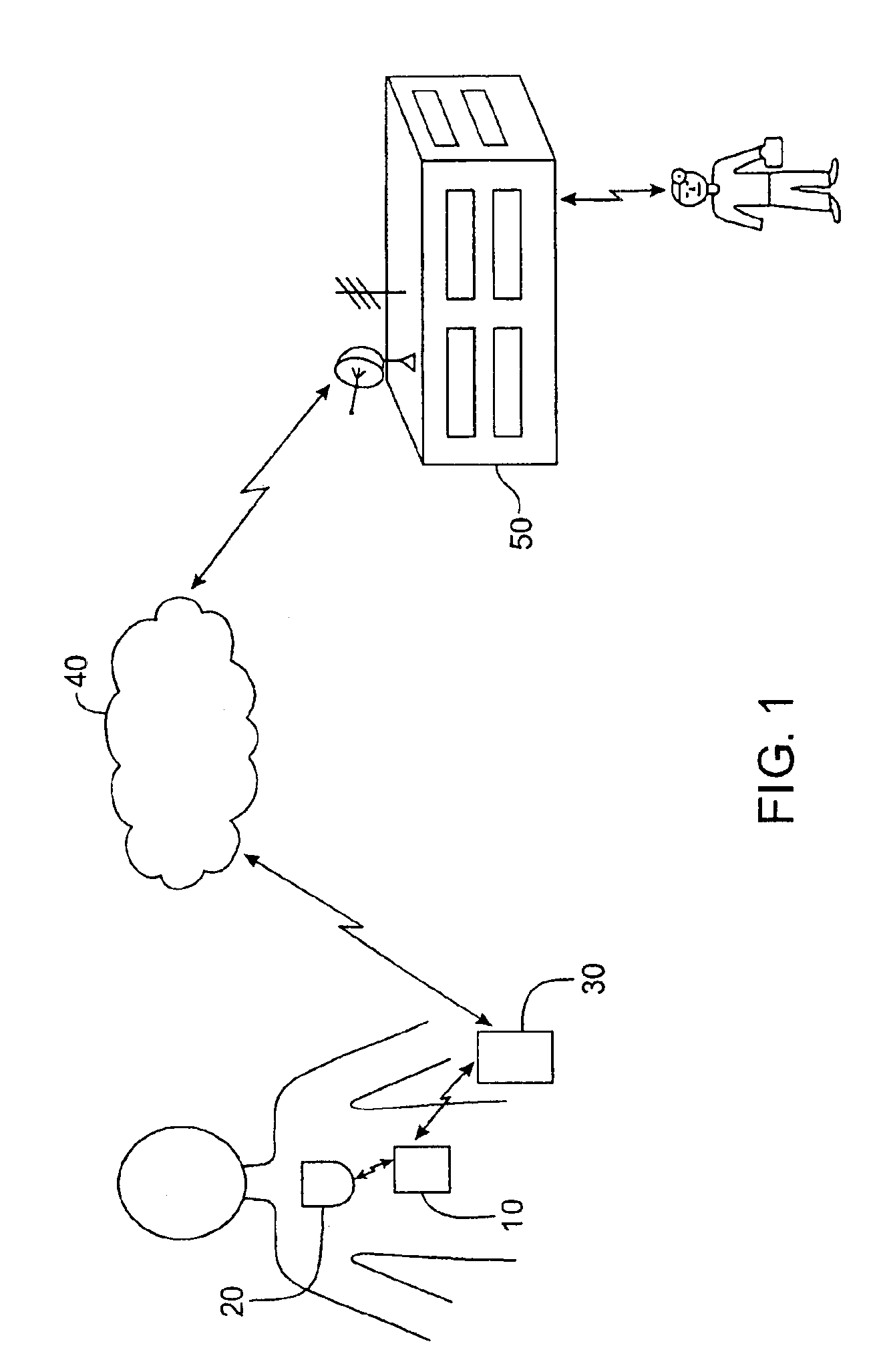
[0034]FIG. 1 illustrates one embodiment of the communication paradigm facilitated by the invention. An implantable transceiver 10 is implanted within a patient's body in close proximity, and so as to and communicate in both directions with, an IMD 20. The implantable transceiver 10 may be physically attached to the IMD 20 or it may be free-floating in the patient's body. The implantable transceiver 10 may otherwise be attached to the patient's body as well. For example, the implantable transceiver 10 may not be implanted within the patient's body, but rather be taped or otherwise secured to the outside of the patients body in close proximity to the IMD 20 within the patient's body. In some embodiments, the implantable transceiver 10 can be mechanically attached to the MD 20, while still using a transceiver to communicate with the IMD 20 and remaining electronically independent. The term “electronically independent” refers to the absence of hard electrical connections and does not ex...


PUM


Abstract

A method and apparatus for communicating with and monitoring the operation of a device implanted within a patient. A transceiver capable of being implanted within a patient provides a communication interface between an implanted medical device and a monitor external to the patient's body. The external monitor can communicate with a remote monitoring center over a communication network. The external monitor also provides control signals to the implanted device via the transceiver unit. The transceiver apparatus is capable of two-way communication between the implanted device and the external monitor. The transceiver apparatus is also capable of detecting actions performed by the implanted device and physiological signals directly from the patient's body. Thus, the transceiver apparatus provides circuitry for determining whether an implanted medical device is operating properly. The transceiver apparatus provides a way to remotely reprogram one or more implanted medical devices.

Description

FIELD OF THE INVENTION[0001]The invention relates to communication systems used to monitor medical devices implanted in a living being. More particularly, the invention relates to a transceiver device which facilitates the remote monitoring and reprogramming of one or more implanted medical devices within a patient.BACKGROUND OF THE INVENTION[0002]Patients that have been identified as having a chronic physical condition, such as a cardiac disorder, are managed in a variety of ways. For some, devices such as a pacemaker or a cardiac defibrillator may be implanted into their body. Implantable medical devices (“IMDs”) may be designed to perform a variety of functions. These functions include stimulation of body organs, drug delivery, and simple monitoring of physiological conditions of a patient. Most IMDs operate independently of any external inputs; but occasionally the devices need to be recharged, reprogrammed, or otherwise checked to ensure proper performance. Typically, a communi...

Claims


Application Information

Patent Timeline
Patent Type & Authority Patents(United States)
IPC IPC(8): A61B5/00A61N1/08
CPCA61B5/0031A61N1/08A61B2560/045Y10S128/904
Inventor ROGERS, BOBBY E.SEVERE, LON M.EGGERS, PHILIP N.
Owner BRAEMAR MFG
Learn More