Reflection photodetector and biological information measuring instrument

a technology of biological information and photodetector, which is applied in the field of reflection photodetector and biological information measuring instruments, can solve the problems of inability to reduce the size of the biological information measuring apparatus, the inability to detect the error easily, and the limitations of conventional biological information measuring apparatuses

Inactive Publication Date: 2001-03-06
SEIKO EPSON CORP
View PDF14 Cites 341 Cited by
  • Summary
  • Abstract
  • Description
  • Claims
  • Application Information

AI Technical Summary

Problems solved by technology

A problem with a conventional biological information measuring apparatus is, therefore, that when it is used where exposed to outside light, such as outdoors, some of the outside light inevitably passes though the finger tissues and reaches the photodetector no matter how large the light shield for blocking outside light is made, and pulse detection errors resulting from variations in the luminance of outside light occur easily.
Such conventional biological information measuring apparatuses are therefore limited to use in places where they are not exposed to outside light, or where the luminance of any outside light is constant.
This limitation can be overcome by using an even larger light shield structure, but the size of the biological information measuring apparatus then cannot be reduced.
There are, however, individual differences in the transmission of outside light, and it is therefore difficult using the above-noted technology to accurately compensate for an outside light component.
It is th

Method used


Image

  • Reflection photodetector and biological information measuring instrument
  • Reflection photodetector and biological information measuring instrument
  • Reflection photodetector and biological information measuring instrument

Examples


embodiment 1

A. Embodiment 1

A-1. Configuration of the First Embodiment

A biological information measuring apparatus according to a first embodiment of the present invention is described below with reference to the accompanying figures.

A-1-1: Overall Configuration

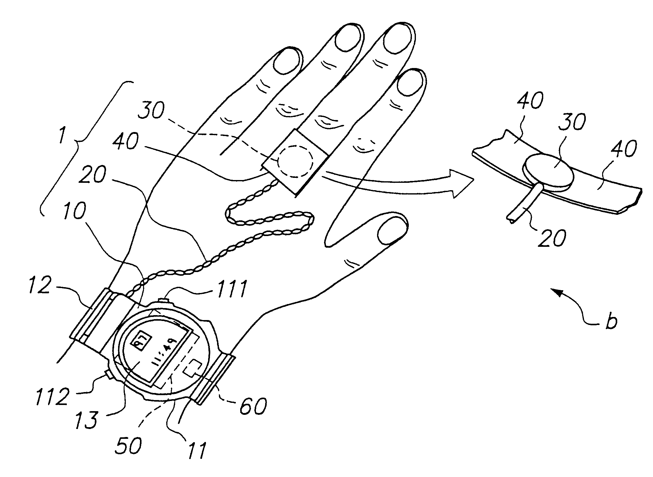
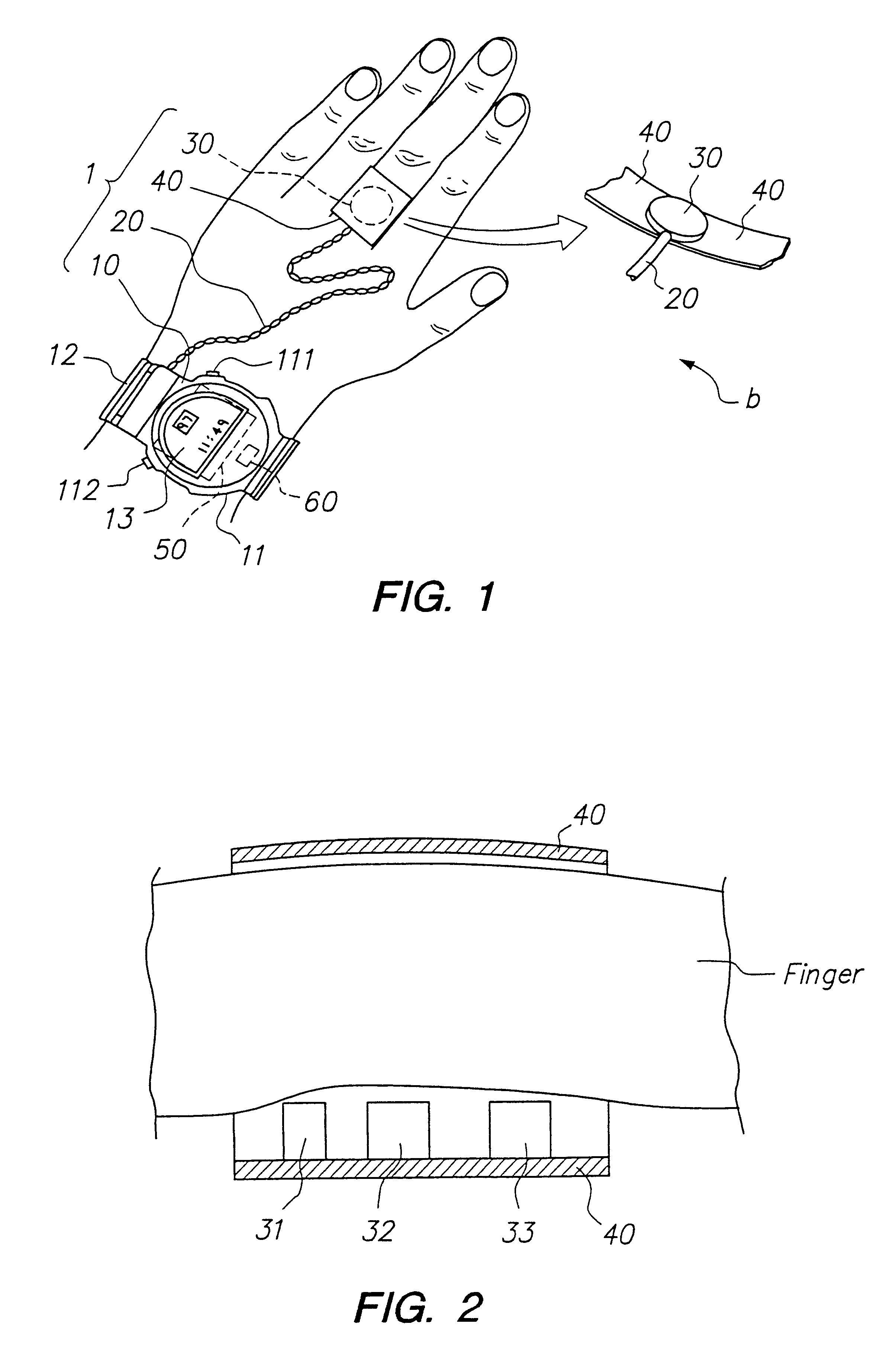
FIG. 1 is an external view of a biological information measuring apparatus according to a first embodiment of the present invention. As shown in this figure, a pulse wave measuring device 1 (biological information measuring apparatus) comprises primarily a main body 10 having a wristwatch construction; a cable 20 leading from this main body; a sensor unit 30 disposed at the end of this cable 20; and a sensor holding band 40 for holding this sensor unit 30 on a finger.

The main body 10 comprises a watch case 11 with a built-in clock function, and a wristband 12 for holding this watch case 11 on the wrist. The surface of the watch case 11 has a liquid crystal display 13 for displaying, in addition to the current time and date, pulse wave inf...

embodiment 2

B. Embodiment 2

The second embodiment of the present invention relates to a body movement measurement device. A body movement measurement device is used to measure body movement by modifying part of the sensor unit 30 (reflection type photodetection apparatus) in the above-described first embodiment of the invention.

B-1. Principle

The body movement signal detection principle of this preferred embodiment is described next. A body movement measurement device according to this preferred embodiment detects body movement using a reflection type optical sensor (sensor unit 300 described below) comprising a photodetection means and light emitting means.

FIG. 20 is for describing the principle of the reflection type optical sensor. Shown in the figure are light emitting means A1 and photodetection means B1, epidermis T1, and blood capillaries and arterioles C1. Body tissues are present between the epidermis T1 and blood vessels C1. Blood flows through blood vessels C1.

Part of the light emitted...

embodiment 3

C. Embodiment 3

A biological information measuring apparatus according to a third preferred embodiment of the present invention is described next with reference to the accompanying figures. This biological information measuring apparatus measures the pulse and other biological information based on a pulse wave signal from which body movement has been removed.

C-1. Configuration of the Third Embodiment

C-1-1: Overall Configuration

FIG. 32 is a section view of a biological information measuring apparatus according to a third embodiment of the present invention. As shown in the figure this biological information measuring apparatus has a wristwatch design. In this exemplary embodiment, sensor unit 301 corresponding to sensor unit 30 in the first embodiment is formed integrally with the main body on the back side of watch case 11. A wristband 12 is attached to the watch case 11 for holding it on the arm; when the wristband 12 is wrapped around the wrist, the back side of the watch case 11 i...


PUM


Abstract

When emitted light from LED 31 is incident on photodiodes 32 and 33 with luminance Pa and Pb, currents ia and ib are generated according to luminance Pa and Pb. When outside light is incident through the finger tissues on photodiodes 32 and 33 with luminance Pc, current ic is produced. The current i1 (=ia+ic) generated by photodiode 32, and the current i2 (=-ib-ic) generated by photodiode 33, are added at node X, and the current ic corresponding to outside light is thus cancelled. In addition, photodiodes 32 and 33 are disposed at different distances from LED 31. As a result, the current flowing to opamp 34 is current ia corresponding to luminance Pa because luminance Pb is extremely low. The opamp 34 then applies a current voltage conversion to generate pulse wave signal Vm.

Description

1. Field of the InventionThe present invention relates to a reflection type photodetection apparatus suitable for detecting the intensity of the reflection of an emitted light reflected by a detected object without being affected by outside light, and relates further to a biological information measuring apparatus comprising this reflection type photodetection apparatus for measuring a pulse wave, pulse, the pitch of body movement or other biological information.2. Description of Related ArtDevices for measuring biological information such as the pulse and body motion include electronic devices for optically detecting a change in blood volume to display biological information based on the detected result. This type of optical pulse wave measuring device (biological information measuring apparatus) emits light from an LED (light emitting diode) or other light emitting element to the finger tip, for example, and detects light reflected from the body (blood vessel) by means of a photod...

Claims


Application Information

Patent Timeline
IPC IPC(8): A61B5/024A61B5/11
CPCA61B5/02416A61B5/02427A61B5/02438A61B5/681A61B5/6826A61B5/6838A61B5/11A61B5/7257A61B2562/0219
Inventor KOSUDA, TSUKASAKONDO, YUTAKAKURIHARA, HAJIMEBABA, NORIMITSU
Owner SEIKO EPSON CORP
Why Eureka
Try Eureka