Implantable generator having current steering means

a technology of implantable generators and steering means, which is applied in the field of devices for programming implantable electrode arrays, can solve the problems of unreasonable large number of possible combinations, unfavorable user experience, and change in optimum stimulation parameters, so as to achieve the effect of easy neural activation patterns, easy programming, and improved neural recruitment efficiency

Inactive Publication Date: 2005-06-21
BOSTON SCI NEUROMODULATION CORP
View PDF26 Cites 339 Cited by
  • Summary
  • Abstract
  • Description
  • Claims
  • Application Information

AI Technical Summary

Benefits of technology

[0024]It is thus a feature of the present invention to provide a system and a method for programming that allows a clinician or patient to quickly determine a desired electrode stimulation pattern, including which electrodes of a multiplicity of electrodes in an electrode array should receive a stimulation current, the polarity, distance between anodes and cathodes, and distribution of stimulation intensity or amplitude.
[0025]It is another feature of the invention to provide an electrode selection system that allows the user (the person operating the programmer) to readily select and visualize a particular group of electrodes of an electrode array for receipt of a stimulation pulse current, and when selected to allow different combinations of pulse amplitude, pulse width, pulse repetition rate, or other pulse-defining parameters to be applied to the selected group.
[0026]It is yet an additional feature of the invention to allow an implantable tissue stimulator, having an array of stimulation electrodes attached thereto, to be readily and quickly programmed so that only those electrodes which prove most effective for a desired purpose, e.g., pain relief, are selected and configured to receive a pulsed current having an amplitude, width, repetition frequency, or burst parameters that best meets the needs of a particular patient.
[0027]It is still another feature of the invention to provide a system and a method of steering or programming the perceived paresthesia so that any needed redistribution of the stimulus current occurs in small step sizes, thereby making neural recruitment more effective. In accordance with this feature of the invention, the small step size in current or voltage amplitude settings that is used amongst the electrode contacts is selected to effectively correspond to the spatial resolution to which neural elements can be activated. That is, this spatial resolution is meaningful to the extent that the micro-anatomy of the neural structures being activated gives rise to different clinical effects. Advantageously, by using such a system that automatically redistributes current or voltage amplitudes amongst electrodes in suitable small step sizes, desired neural activation patterns may be found more easily.
[0028]It is another feature of the invention to provide a system for redistributing current and / or voltage amplitudes amongst selected electrodes using a user interface that is simple and intuitive.
[0029]It is an object of the invention to eliminate the need for either a clinician to manually select electrode combinations, or even for a computer to select electrode combinations that must be discretely tested for patient feedback. That is, based on the feedback as to the amount of coverage, an educated guess for another combination must be made (by clinician or computer) and the patient must then discretely respond to that combination before another combination is set up and turned on. Such discrete testing with patient feedback is very tedious and time consuming. Advantageously, by practicing the present invention, discrete selection and patient feedback of location and amount of paresthesia coverage (either to the clinician or to a computer) is avoided.

Problems solved by technology

For example, if the pulse amplitude is set too low, there may be insufficient pain relief for the user; yet, if the pulse amplitude is set too high, there may be an unpleasant or uncomfortable stinging or tingling sensation felt by the user.
Moreover, the optimum stimulation parameters may change over time.
For an electrode array having eight electrode contacts, this can result in an unreasonable large number of possible combinations, or stimulation groups, to chose from.
Disadvantageously, it is difficult to test many stimulation variables with hundreds or even thousands of possible electrode and stimulus parameter combinations.
To test all such combinations, which is typically necessary in order to find the optimum stimulation settings, is a very lengthy and tedious process.
Because an all-combination test is lengthy and tedious, some clinicians may not bother to test many different electrode combinations, including many that may be considered far more optimal than what is ultimately programmed for the patient.
Moreover, the physician / clinician is not directly controlling the programming session; rather, the patient provides the system with the feedback without the need for the physician or clinician to interpret the patient's sensations or empirically estimate changes required in stimulation parameters.
Disadvantageously, using the method described in the '672 patent, the patient must still test and respond to each of the chosen combinations and must depend upon the system recommendations, which system recommendations might exclude a possible optimal setting for that patient.
Such process can still be time consuming.
Hence, the process of computer-recommended combinations, although superior to manual arbitrary selection, can still be viewed as an undesirable “discrete” method of patient feedback evaluation: i.e., electrodes are programmed and patient feedback is entered for each combination, one iteration at a time.

Method used


Image

  • Implantable generator having current steering means
  • Implantable generator having current steering means
  • Implantable generator having current steering means

Examples


Embodiment Construction

[0052]The following description is of the best mode presently contemplated for carrying out the invention. This description is not to be taken in a limiting sense, but is made merely for the purpose of describing the general principles of the invention. The scope of the invention should be determined with reference to the claims.

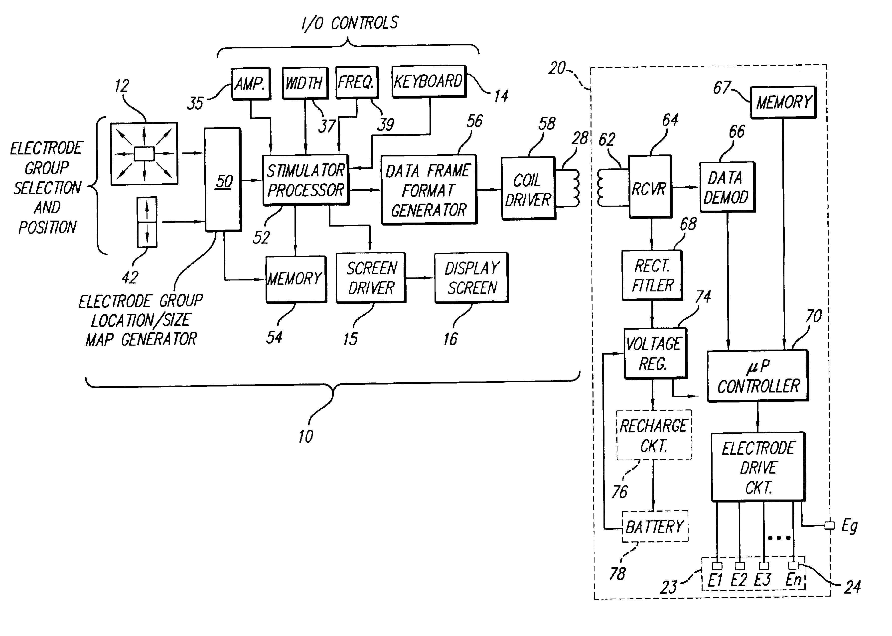
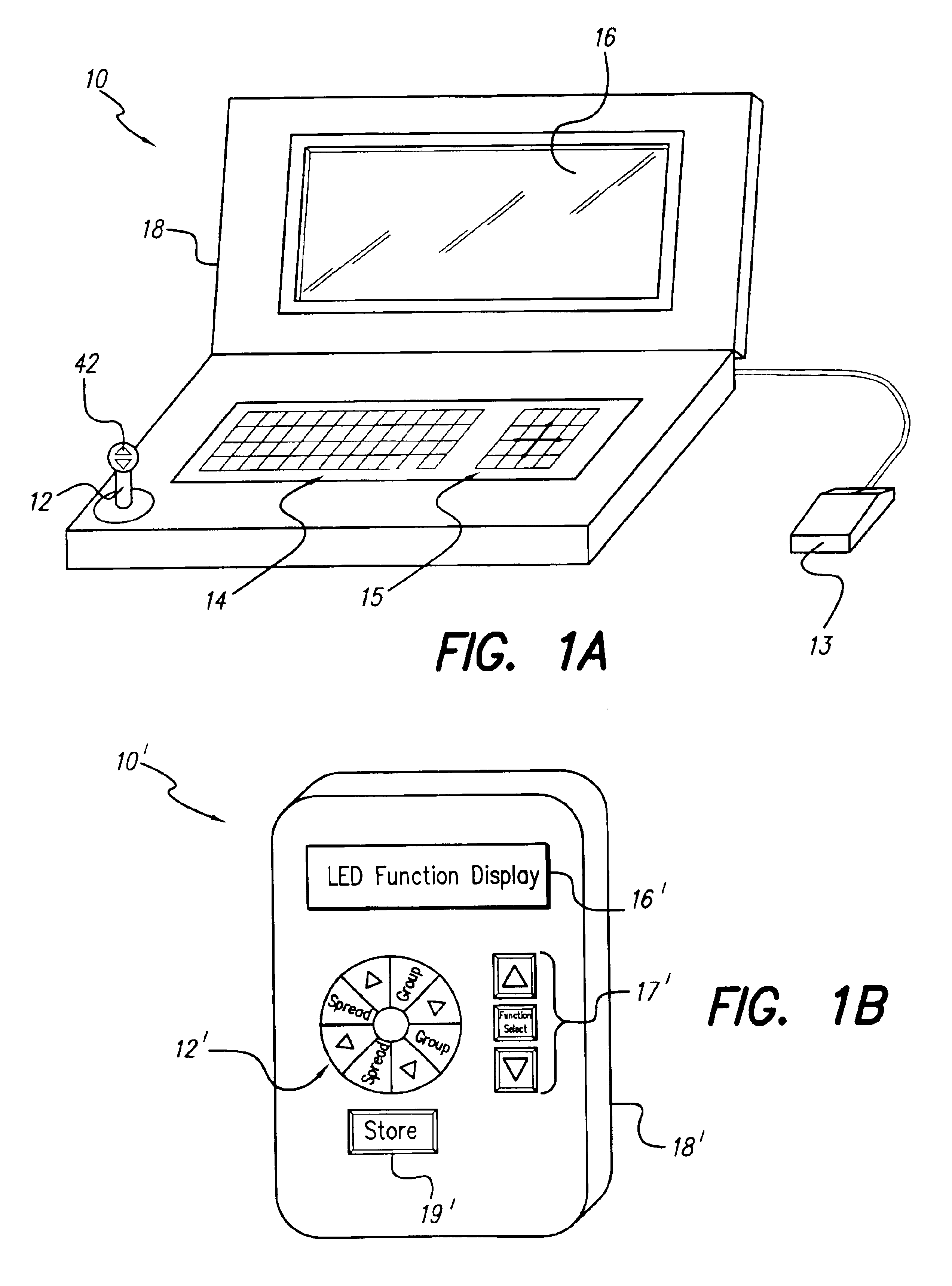
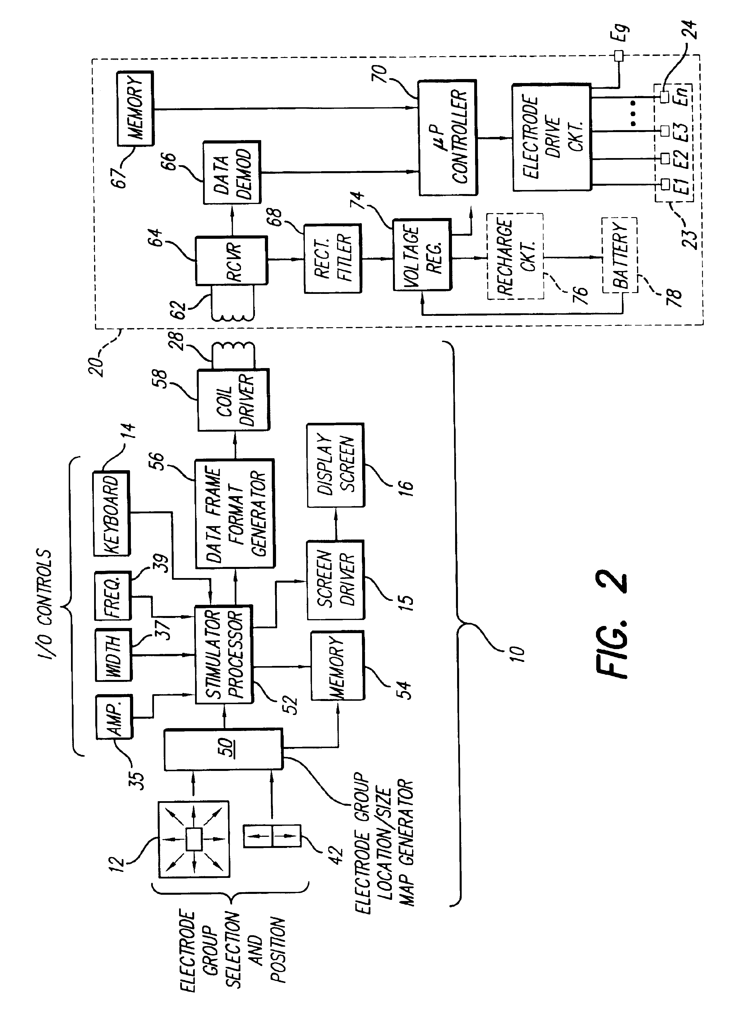
[0053]At the outset, it is to be noted that a preferred implementation for a directional programming device in accordance with the present invention is through the use of a joystick-type device or equivalent. Hence, in the description that follows, a joystick device is described. It is to be understood, however, that other directional-programming devices may also be used in lieu of a joystick, e.g., a roller ball tracking device, horizontal and vertical rocker-type arm switches, selected keys (e.g., directional-arrow keys) on a computer keyboard, touch-sensitive surfaces on which a thumb or finger may be placed, recognized voice commands (e.g., “up”, “down”,...


PUM


Abstract

An implantable pulse generator includes a current steering capability that allows a clinician or patient to quickly determine a desired electrode stimulation pattern, including which electrodes of a group of electrodes within an electrode array should receive a stimulation current, including the amplitude, width and pulse repetition rate of such current. Movement of the selected group of electrodes is facilitated through the use of remotely generated directional signals, generated by a pointing device, such as a joystick. As movement of the selected group of electrodes occurs, current redistribution amongst the various electrode contacts takes place. The redistribution of stimulus amplitudes utilizes re-normalization of amplitudes so that the perceptual level remains fairly constant. This prevents the resulting paresthesia from falling below the perceptual threshold or above the comfort threshold.

Description

[0001]This application is a continuation of U.S. application Ser. No. 10 / 150,879 filed May 17, 2002, now U.S. Pat. No. 6,609,032; which application is a continuation of Ser. No. 09 / 550,217, filed Apr. 17, 2000, now U.S. Pat. No. 6,393,325; which application is a continuation-in-part of U.S. patent application Ser. No. 09 / 226,849, filed Jan. 7, 1999, now U.S. Pat. No. 6,052,624; which application claims the benefit of the following U.S. Provisional Applications: Ser. No. 60 / 145,829, filed Jul. 27, 1999, and Ser. No. 60 / 172,167, filed Dec. 17, 1999; which applications and patents are incorporated herein by reference.BACKGROUND OF THE INVENTION[0002]The present invention relates to a device for programming an implantable electrode array used with an implantable stimulator. More particularly, one embodiment of the invention relates to a device used to provide directional programming for the implantable electrode array associated with an implantable stimulator that electrically stimulate...

Claims


Application Information

Patent Timeline
Patent Type & Authority Patents(United States)
IPC IPC(8): A61N1/372
CPCA61N1/37247
Inventor WOODS, CARLA MANNPETERSON, DAVID K. L.MEADOWS, PAUL M.LOEB, GERALD E.
Owner BOSTON SCI NEUROMODULATION CORP
Why Eureka
Try Eureka