Mounting platform assembly for a stand device

a technology for mounting platforms and stand devices, which is applied in the direction of washstands, scaffold accessories, lightening support devices, etc., can solve the problems of inconvenient above operation, camera or video camera needs to be supported, and reporter or ecological photographer may miss very important scenes, etc., and achieve the effect of fast positioning

Inactive Publication Date: 2007-03-06
YANG ZHENYU
View PDF9 Cites 125 Cited by
  • Summary
  • Abstract
  • Description
  • Claims
  • Application Information

AI Technical Summary

Benefits of technology

[0007]The objective of the present invention is to provide a mounting platform assembly for a stand device, which is capable of fast positioning and fixing an object, such as a camera, to the stand device.

Problems solved by technology

However, the hands of the user may shake or sway so as to make the resulted pictures vague.
Especially, some bulkier and heavier cameras or video cameras need to be supported by stand devices to smooth the shooting.
As a result, no matter assembling or disassembling, the above operation is very inconvenient.
In some cases having special requirements, for example, a reporter or ecological photographer may miss very important scenes if he or she does not complete the assembling of the camera as soon as possible and timely take the shoot.
Although a mounting platform assembly, which has been changed to a sliding-type structure and can be fast assembled with a camera, is proposed, they are not provided with any safety positioning means.
Thus, the camera connected thereon is liable to slide out of the mounting platform assembly.
It still has a problem not able to achieve the safe fixation of the camera.

Method used


Image

  • Mounting platform assembly for a stand device
  • Mounting platform assembly for a stand device
  • Mounting platform assembly for a stand device

Examples


Embodiment Construction

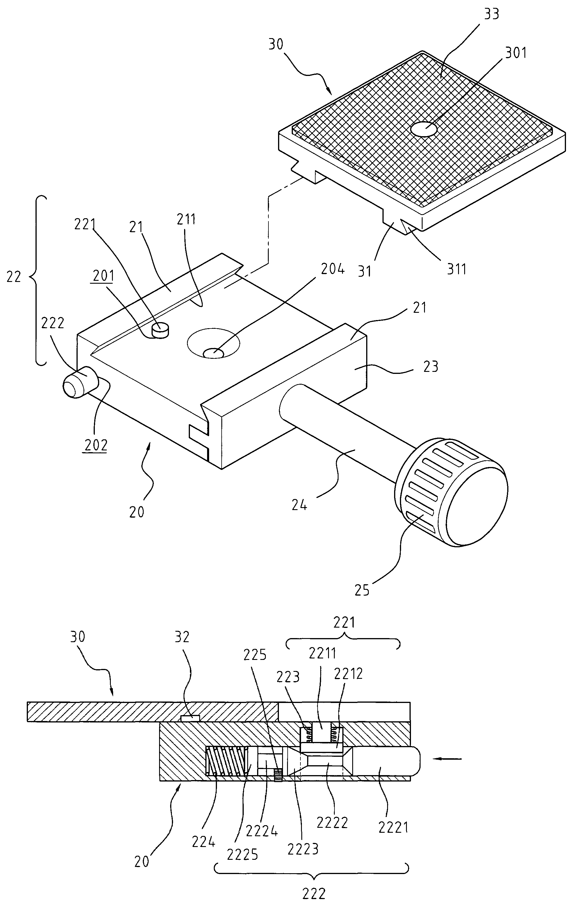
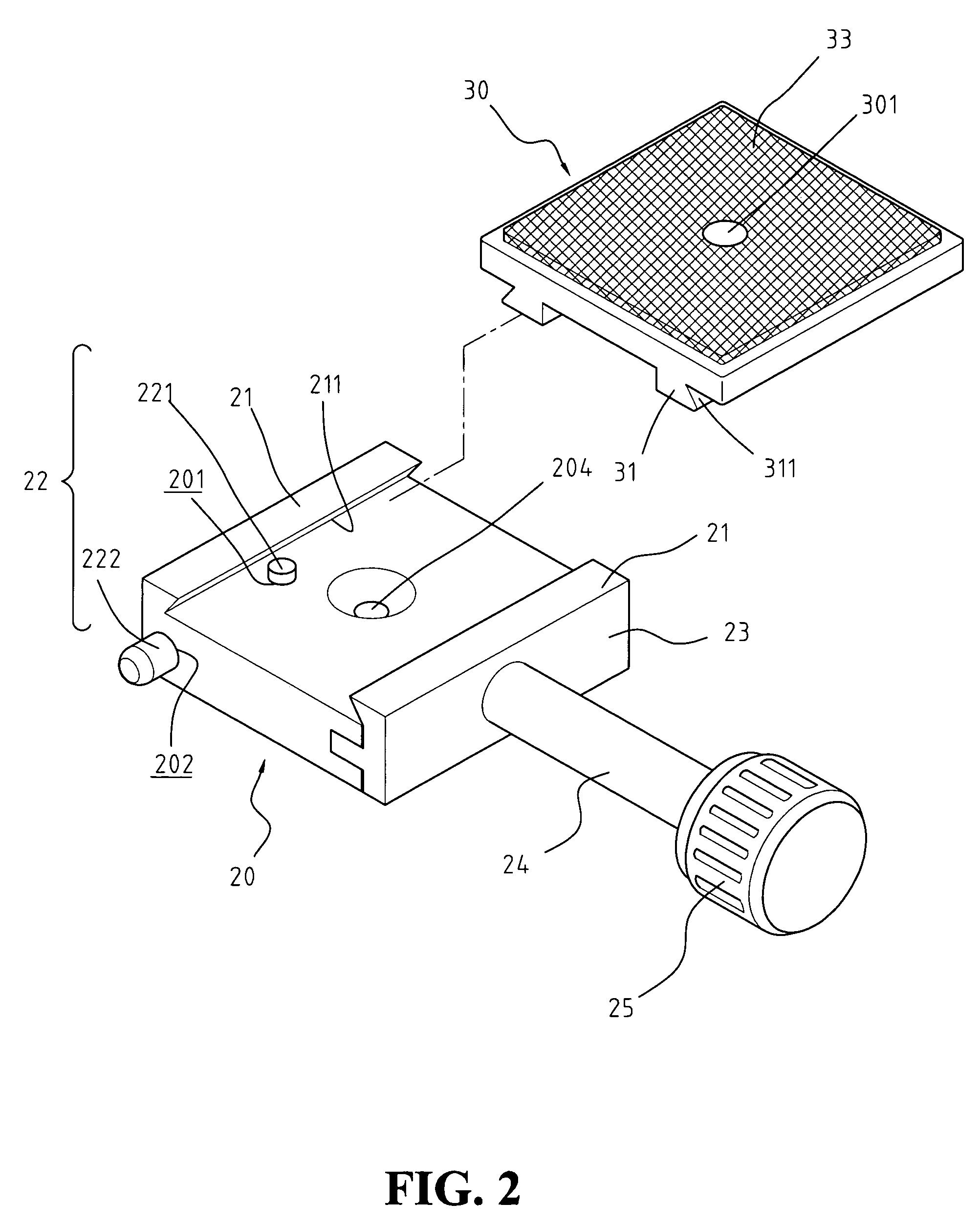
[0018]With reference to FIG. 2, a mounting platform assembly for a stand device in accordance with the present invention comprises a fixing base 20 and a connecting platform 30. The connecting platform 30 having two male engaging blocks 31 engages with two sliding grooves 211 of the fixing base 20; and, by the engagement of a positioning hole 32 on the male engaging block 31 and an engaging button 221 on a top surface the fixing base 20, the connecting platform 30 can be firmly fixed on the fixing base 20.

[0019]Next, with reference to FIGS. 2 and 3, the fixing base 20 is provided with two engaging ribs 21 projecting from the top surface thereof. Faces of the engaging ribs 21 opposite to each other are provided with a slope and thus form a sliding groove 211 on the top surface of the fixing base 20, respectively. The fixing base 20 is laterally provided with a transverse notch 202 in communication with a through hole 201 perpendicularly provided on the fixing base 20. The through hol...


PUM


Abstract

A mounting platform assembly for a stand device includes a connecting platform having two parallel engaging blocks projecting from a bottom surface thereof, each having a positioning hole and forming a slope on an outward face thereof; and a fixing base having two engaging ribs projecting from a top surface thereof, each forming a sliding groove on the top surface of the fixing base corresponding to the slope of each engaging block, and the fixing base having a positioning means including an engaging button and a push rod. When a conical portion of the push rod abuts against a bottom end of the engaging button, the other end of the engaging button projects from the top surface of the fixing base to engage with the positioning hole of the engaging block, thereby achieving the positioning and fixing of the connecting platform.

Description

BACKGROUND OF THE INVENTION[0001]1. Field of the Invention[0002]The present invention relates to a mounting platform assembly for a stand device, which is capable of fast positioning and fixing an object, such as a camera, to the stand device.[0003]2. The Prior Arts[0004]In general, when using a camera or video camera to photo or shoot, a user usually holds the camera or video camera by hands. However, the hands of the user may shake or sway so as to make the resulted pictures vague. Therefore, in order to keep the stability in taking a photograph, a mounting platform assembly is often used to fix the camera to a stand device. After the camera has been fixed, it can be used to stably shoot by time lapse or remote control. Especially, some bulkier and heavier cameras or video cameras need to be supported by stand devices to smooth the shooting. Also, the camera to be fixed to a stand device is often mounted to a mounting platform assembly.[0005]Referring to FIG. 1, a conventional mou...

Claims


Application Information

Patent Timeline
Patent Type & Authority Patents(United States)
IPC IPC(8): F16M11/04
CPCF16M11/02F16M11/04F16M13/00F16M11/041F16M2200/028
Inventor YANG, JEN YU
Owner YANG ZHENYU
Why Eureka
Try Eureka