Method and system for automated selection of optimal communication network equipment model, position, and configuration

Inactive Publication Date: 2006-05-30
EXTREME NETWORKS INC
View PDF114 Cites 131 Cited by
  • Summary
  • Abstract
  • Description
  • Claims
  • Application Information

AI Technical Summary

Benefits of technology

[0057]According to the present invention, a system is provided for allowing a communication system designer to dynamically model a three dimensional environment of a building, campus, city, or any other physical environment electronically in a manner suitable for the prediction of communication system performance. A system is also provided for allowing a communication system designer to dynamically model a communication system for a building, campus, city or other environment electronically. The method includes the selection and placement of various commercial hardware components, such as antennas (point, omni-directional, leaky feeders, etc.), transceivers, amplifiers, cables, routers, connectors, couplers, splitters, hubs, or any other single or composite communication hardware device utilized as part of any baseband, RF, or optical communication network, or any combination of the above, and allows the user to observe the effects of their placement and movement at other locations or watch points chosen by the designer. Thus, the placement of components can be refined and fine tuned prior to actual implementation of a system to ensure that all required areas of the facility are provided with adequate commu

Problems solved by technology

The importance of communication network performance has quickly become an important design issue for engineers who must design and deploy communication system equipment, telephone systems, cellular telephone systems, paging systems, or new wireless communication systems and technologies such as personal communication networks or wireless local area networks.
A common problem for wireless systems is inadequate coverage, or a “dead zone,” in a specific location, such as a conference room, subway tunnel, or alleyway.
It is now understood that an indoor wireless PBX (private branch exchange) system or wireless local area network (WLAN) can be rendered useless by interference from nearby, similar systems.
The costs of in-building and microcell devices which provide wireless coverage within a 2 kilometer radius are diminishing, and the workload for RF engineers and technicians to install these on-premises systems is increasing sharply.
In practice, however, information regarding a pre-existing building or campus is available only in paper format and a database of parameters defining the environment in a manner suitable for radio wave propagation analysis does not readily exi

Method used


Image

  • Method and system for automated selection of optimal communication network equipment model, position, and configuration
  • Method and system for automated selection of optimal communication network equipment model, position, and configuration
  • Method and system for automated selection of optimal communication network equipment model, position, and configuration

Examples


Example

[0080]The present invention represents a dramatic improvement over prior art by providing the design engineer with an automatic method and system for determining optimal communication equipment models, positions, and configurations within a facility. A detailed description of the general method taken by the present invention follows.

[0081]Using the present method, it is now possible to determine the ideal placement and configuration of communication hardware equipment within a facility in an automated fashion. The current embodiment is designed specifically for use with the SitePlanner Im suite of products available from Wireless Valley Communications, Inc. of Blacksburg, Va. However, it will be apparent to one skilled in the art that the method could be practiced with other products either now known or to be invented.

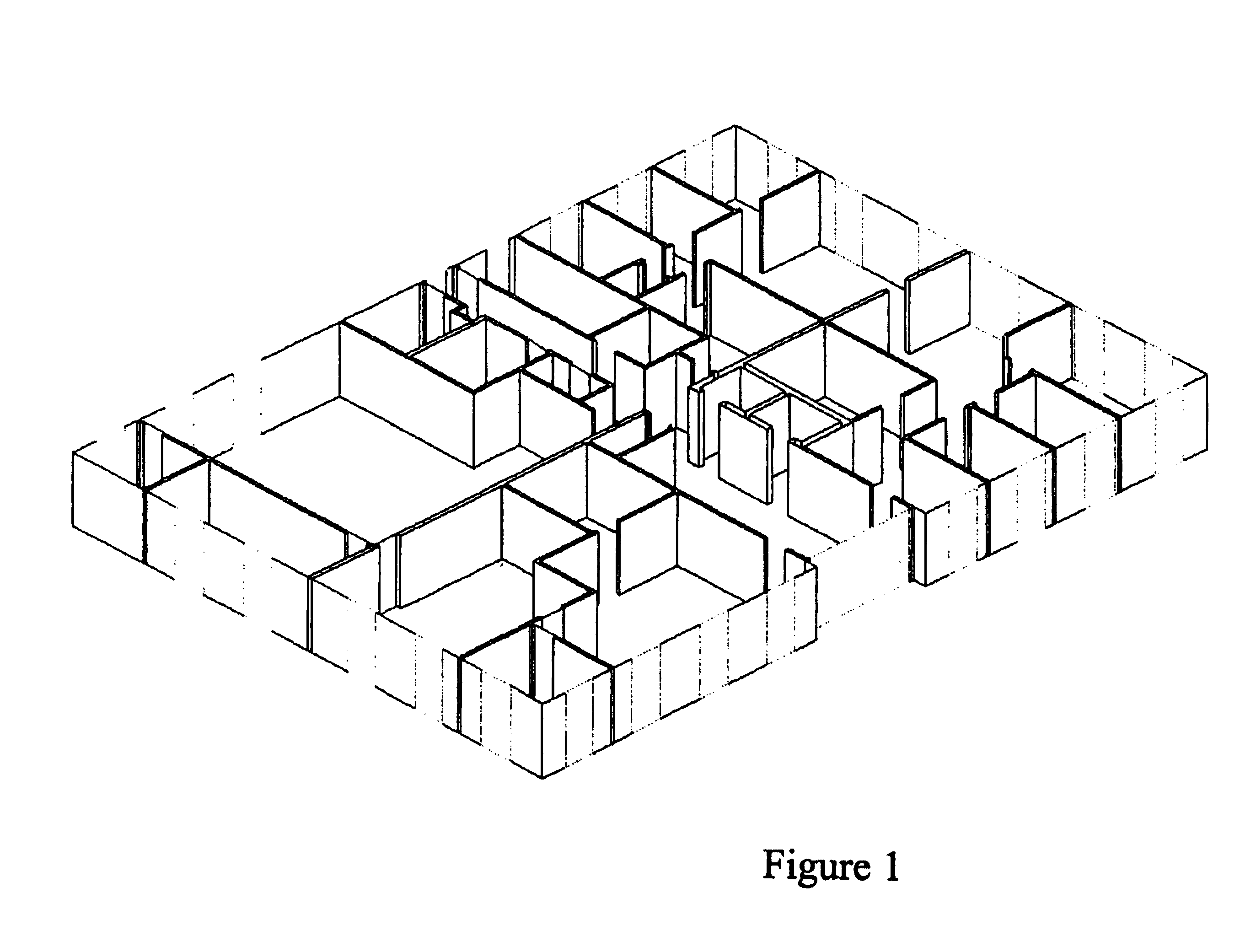
[0082]Referring now to FIG. 1, there is shown a three-dimensional (3-D) simplified example of a layout of a building floor plan. The method uses 3-D computer aided des...


PUM


Abstract

A method for engineering management and planning for the design of a communications network in three dimensions (3-D) combines computerized organization, database fusion, and site-specific communication system performance prediction models. The method enables a designer to keep track of communication system performance through the process of pre-bid, design, installation and maintenance of a communication system. Automated selection, placement and configuration of communication component equipment can be performed using desired performance criteria identified at finite locations within the environment along with a finite set of communication component models and suitable locations and configurations in the environment.

Description

CROSS-REFERENCE TO RELATED APPLICATIONS[0001]This application is related to pending application Ser. No. 09 / 318,842, entitled “Method and System for Managing a Real Time Bill of Materials,” filed by T. S. Rappaport and R. R. Skidmore, Ser. No. 09 / 318,841, entitled “Method And System for a Building Database Manipulator,” filed by T. S. Rappaport and R. R. Skidmore, Ser. No. 09 / 318,840, entitled “Method and System For Automated Optimization of Communication component Position in 3D” filed by T. S. Rappaport and R. R. Skidmore, Ser. No. 09 / 633,122 entitled “Method and System for Designing or Deploying a Communications Network which Allows Simultaneous Selection of Multiple Components” filed by T. S. Rappaport and R. R. Skidmore, Ser. No. 09 / 633,121, entitled “Method and System for Designing or Deploying a Communications Network which Considers Frequency Dependent Effects” filed by T. S. Rappaport and R. R. Skidmore, Ser. No. 09 / 632,853, entitled “Method and System for Designing or Depl...

Claims


Application Information

Patent Timeline
IPC IPC(8): G09G5/00G06F17/50H04L12/24H04W16/18
CPCH04L41/145H04L41/22H04W16/20H04L41/147Y10S715/964G06F15/173
Inventor RAPPAPORT, THEODORESKIDMORE, ROGERSHEETHALNATH, PRAVEEN
Owner EXTREME NETWORKS INC
Why Eureka
Try Eureka