Optical fiber sensor system

a technology of optical fiber and sensor system, applied in the field of optical fiber sensor system, can solve the problems of inflexible and expensive ability to detect different parameters of prior systems which employ such sensors, inability to detect different parameters, and high volume and weight, so as to reduce system weight and size, reduce weight, and reduce cost

Inactive Publication Date: 2001-03-20
MCDONNELL DOUGLAS
View PDF6 Cites 143 Cited by
  • Summary
  • Abstract
  • Description
  • Claims
  • Application Information

AI Technical Summary

Benefits of technology

The invention meets the above needs and overcomes the deficiencies of the prior art by providing an optical fiber sensor system which uses only one light source in combination with multiple arrays of sensors. The invention accomplishes this by employing a tunable light source which is multiplexed to address the sensors of the multiple arrays. The tunable light source of the invention reduces system weight and size so that systems according to the invention meet the need for an optical fiber sensor system which has a reduced weight and a miniaturized package of reduced cost. This invention is also directed to meeting the need for such a system which employs a single light source so that its cost is reduced without a loss in flexibility or accuracy.
In particular, the inventors have taken advantage of the advent of brighter low cost tunable light sources and have addressed the cost problem at the source (i.e., in the section of the layout prior to the light reaching the sensors) rather than at the detector (i.e., in the section after the light leaves the sensors on its way to the detectors), as most prior art has done. This invention provides an optical fiber sensor system which uses one tunable source of light to all the sensors. The single tunable source allows the elimination of many tunable filters located before the photodetectors and peak detectors as in the prior art. This results in a size and weight savings as well as an increase in reliability.
Even though the system of the invention employs a single tunable light source, the invention provides light to a plurality of sensors operating within different bandwidths. This overcomes the limitations of the prior art systems and provides a flexibility not previously recognized in the prior art. Consequently, the invention becomes particularly useful in high performance, low cost Bragg grating sensor systems.
Another advantage of the optical fiber sensor system of the invention is that it allows sensor systems to employ Bragg grating sensors in combination with a digital signal processor. Because the processor according to the invention need only process a reduced number of data points per trace, the processor quickly determines peaks so that the system is higher in speed.
The low cost and low weight advantages of the optical fiber sensor system of the invention provide a system that is useful in monitoring structural integrity over time. In particular, systems of the invention provide substantially continuous monitoring of vibration, strain, wear and other parameters. Furthermore, such parameters can be monitored in fixed structures such as bridges as well as mobile structures such as aircraft.
The adaptability of the invention also provides an optical fiber sensor system for use in telecommunications such as substation to substation communication. The flexibility of the invention also has advantages in that it provides a system which can meet a rising market need for more sensors per system while being useful in both commercial and military markets. In addition, the invention provides an optical fiber sensor system which uses simple strain gauges and provides full health monitoring of structural integrity of stationary as well as mobile systems.

Problems solved by technology

However, the prior systems which have employed such sensors have been very expensive and inflexible in their ability to detect different parameters.
In addition, such prior systems were high in volume and weight (e.g., large and heavy) which made them unacceptable in mobile applications.
Such systems have been found to be very expensive, primarily because of the cost associated with the various light sources needed to illuminate each sensor array with light of the appropriate bandwidth and multiple tunable filters to locate the sensors.
In addition, the need for various or multiple light sources tends to add the significant weight and volume of such prior art systems which limit the applicability of the system for use in mobile applications or other environments in which a light weight or compact monitoring system is needed or desired.

Method used


Image

  • Optical fiber sensor system
  • Optical fiber sensor system
  • Optical fiber sensor system

Examples


Embodiment Construction

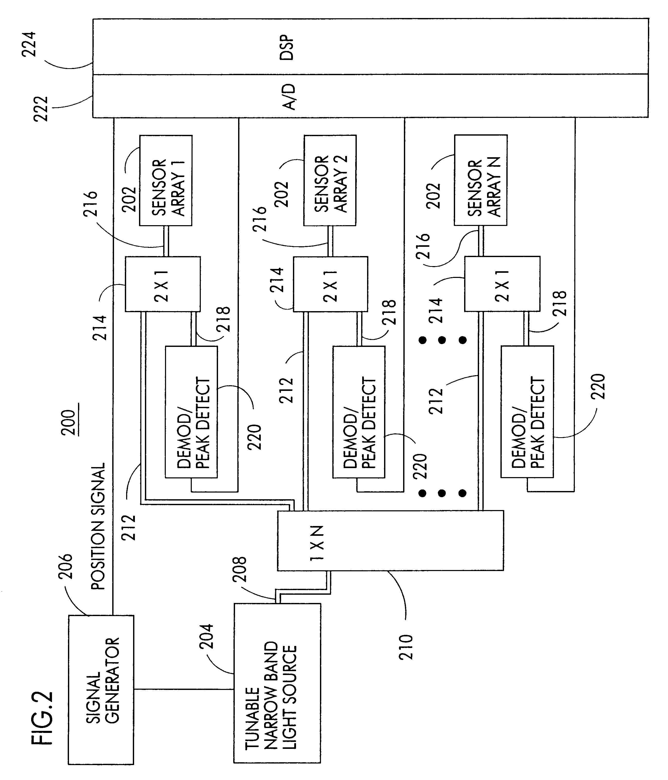
Referring to FIG. 2, a block diagram of one preferred embodiment of an optical fiber sensing system 200 according to the invention including N sensor arrays 202 is illustrated. Although the system 200 is illustrated as having N channels, it is contemplated that it may have one or more channels. Preferably, each array 202 is a plurality of Bragg grating sensors either connected in series (in line) or in parallel.

Each sensor of the array 202 is configured to transmit data or sense a particular or different parameter of the device being monitored at various locations. For example, if the system 200 is monitoring an aircraft, a first sensor of array 202 may be a Bragg grating sensor which detects strain at a first location; a second sensor of array 202 may be a Bragg grating sensor which detects strain at a second location; a third sensor of array 202 may detect temperature and so on. It is also contemplated that Bragg sensors may be used to detect other parameters, such as corrosion or...


PUM

PropertyMeasurementUnit
wavelengthaaaaaaaaaa
FWHMaaaaaaaaaa

Abstract

A system such as for sensing strain or temperature of an aircraft and for transmitting information in communication systems. A sensor array includes a first light responsive Bragg grating sensor having a first operating bandwidth and a second light responsive Bragg grating sensor having a second operating bandwidth. Each sensor modifies light provided to it at a wavelength indicative of changes in strain or temperature. The second sensor operates within a bandwidth which is different from the operating bandwidth of the first sensor. A tunable light source such as an LED and tunable etalon provides light for illuminating the first and second sensors, the provided light having a wavelength which varies within a band including the first and second bandwidths. A detecting circuit provides signals representative of light modified by the first and second sensors. A processor processes the representative signals to determine the strain and / or temperature.

Description

The invention generally relates to sensing systems and, in particular, an optical fiber sensor system having multiple light responsive sensors for sensing various parameters and for use in communication systems.Fiber optic intracore Bragg gratings have been used in prior sensing systems as reliable, localized sensors of strain, temperature and other physical parameters. The wavelength encoding of strain and temperature in these Bragg grating sensors make them suited for monitoring structures to track strain and temperature over periods of time. Such sensors are not affected by electrical interference as compared to electrical based sensors. However, the prior systems which have employed such sensors have been very expensive and inflexible in their ability to detect different parameters. In addition, such prior systems were high in volume and weight (e.g., large and heavy) which made them unacceptable in mobile applications.An example of such a prior art two channel system employing ...

Claims


Application Information

Patent Timeline
Patent Type & Authority Patents(United States)
IPC IPC(8): G01D5/353G01L1/24G01D5/26
CPCG01D5/35383G01L1/246
Inventor ELLERBROCK, PHILIP J.BELK, JOHN H.JOHNSON, BARTLEY C.
Owner MCDONNELL DOUGLAS
Why Eureka
Try Eureka