Heart valve annulus device and method of using same

a heart valve and annulus technology, applied in the field of prosthetic heart valve anchors, can solve the problems of heart valve damage, needing complete valve replacement, and requiring complete valve replacement, so as to reduce the overall time required, improve the maneuverability, and minimize the time-consuming process of suturing

Inactive Publication Date: 2005-05-17
VENTURE LENDING & LEASING IV
View PDF31 Cites 681 Cited by
  • Summary
  • Abstract
  • Description
  • Claims
  • Application Information

AI Technical Summary

Benefits of technology

[0023]As can be seen, the heart valve anchor of the present invention takes advantage of mechanical retainers to minimize the time consuming process of suturing the valve anchor into place, thereby greatly reducing the overall time necessary to complete the surgical procedure. Such anchor offers the advantage that it can be implanted separate and independent of the occluder thus enhancing its maneuverability and providing ready visual and physical access thereto for ease of placement and mounting of the occluder. Similarly, the heart valve anchor of the present invention solves a variety of problems associated with suture techniques including reduced valve size, pannus creep, and the in-growth of fibrosis which can cause valve failure. Furthermore, this procedure may be utilized without subjecting the patient to open chest surgery which reduces the incidence of infection to the patient in addition to the obvious reduction in the overall trauma experienced by the body.

Problems solved by technology

It is well known that a variety of medical conditions and diseases may cause damage to the heart valve which ultimately necessitates valve replacement.
If these defects are not corrected, prolonged valvular stenosis or insufficiency may cause damage to the heart muscle and may even require complete valve replacement.
However the failure rate of these bioprosthetic valves is at 15% by fifteen years after surgery, and therefore these tend to require periodic replacement.
While heart valve implants have become widely accepted in the medical field, this procedure is still extremely costly.
In addition to the expensive personnel, valve implant surgery requires extensive operating time which is both costly and subjects the patient to a greater health risk the longer he is on a bypass machine and under anesthesia.
While there are a variety of advantages to this standard means of sewing the heart valve into orthotopic or heterotopic positions, there still remain a vast number of disadvantages which make an alternative means desirable to find.
Furthermore, suture placement itself can be a tedious process which often demands a significant portion of the overall operation time.
Accurate placement and orientation of the valve within the heart is a difficult and high risk aspect of this procedure which may be minimized by enlarging the chest openings, giving the surgeon better access and increasing the prospect that the valve will be placed successfully.
For most cardiovascular surgeries, the need for precise suturing for securement of the heart valve prosthetic has been difficult to improve upon.
Therefore, while adequate access to the chest cavity has been considered necessary during heart valve replacement, it is an extremely traumatic event for the patient and subjects them to a higher risk of infection.
Additionally, suturing the prosthesis valve into the heart muscle creates a subsequent problem for the patient due to the fact that the valve itself is bulky, and when sutured into place, the suturing process necessarily reduces the cross section of the flow path through the valve body.
Such a flow restriction may adversely affect blood flow which may increase the transvalvular pressure gradients of the heart thereby requiring it to work harder to pump the same volume of blood.
For a patient already experiencing heart stress, the increased pressure on the heart is clearly undesirable.
However, the result is that the tissue becomes constricted at the site of the implant.
Another problem with the suturing technique is a tendency to constrict the heart annulus.
Other problems associated with suturing of the valve prosthetic occur when the suture is placed too deeply into the muscle wall.
When the suture extends deep into the muscle wall, the suture can catch the back wall of a contiguous structure thereby causing damage to that tissue or otherwise injuring the cardio-conduction system which may result in conduction abnormalities.
Similarly, sutures securing a valve in place may cause the formation of blood clots due to the presence of additional foreign objects in the body.
The danger caused by these blood clots can be severe if a clot breaks away and enters the patient's blood stream, thereby causing a major health problem such as a heart attack or stroke.
Additionally, the very nature of sutures creates problems because when the surgeon stitches the sew cuff in place, he or she knots and cuts the thread leaving raw edges somewhat exposed to the patient's blood stream.
Due to the location of these potential blood clots, a formed clot may even extend into the valve itself thus trapping it open or shut and generally causing overall valve malfunctions.
It has also been observed that the presence of foreign materials in the body, such as sutures and staples, increases the potential for bacterial infection at that site.
Without a secure fit between the prosthetic and the tissue, leaks may develop between the valve anchor and heart annulus thereby allowing blood to bypass the valve.
Such a situation may be disastrous.
Such devices, while offering interesting solutions, are relatively complex and have not gained general acceptance in the field.
Furthermore, the use of staples instead of sutures has been known to exhibit similar scarring and tension effects.
While relatively effective in solving certain problems, such an assembly is fairly large and cumbersome as well as being mechanically complex.
A device of this nature, while effective to grip a conventional cuff, does not provide for mechanical anchoring of the cuff to the annulus or provide for an arrangement for deployment of a mechanically anchoring device.

Method used


Image

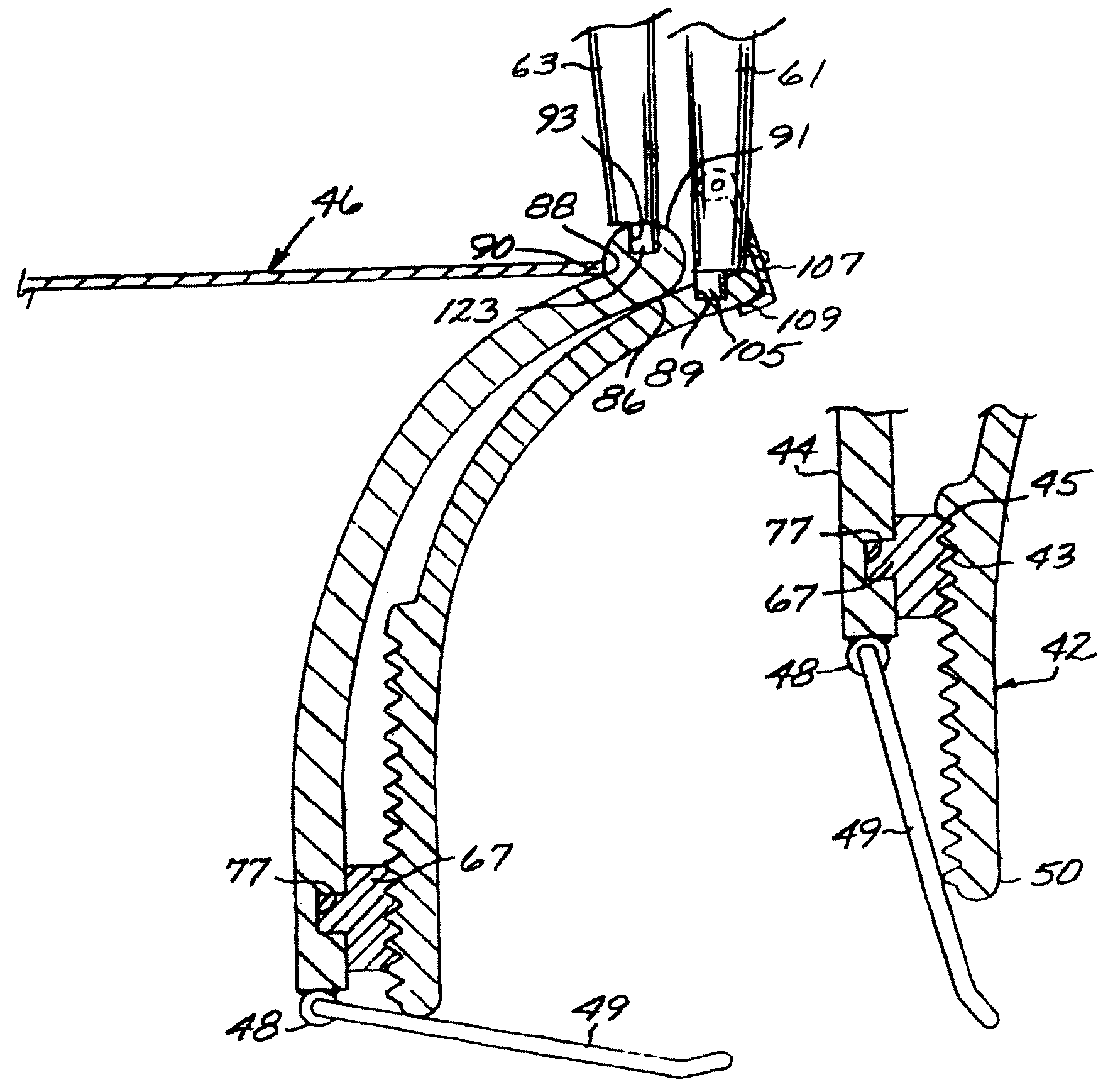
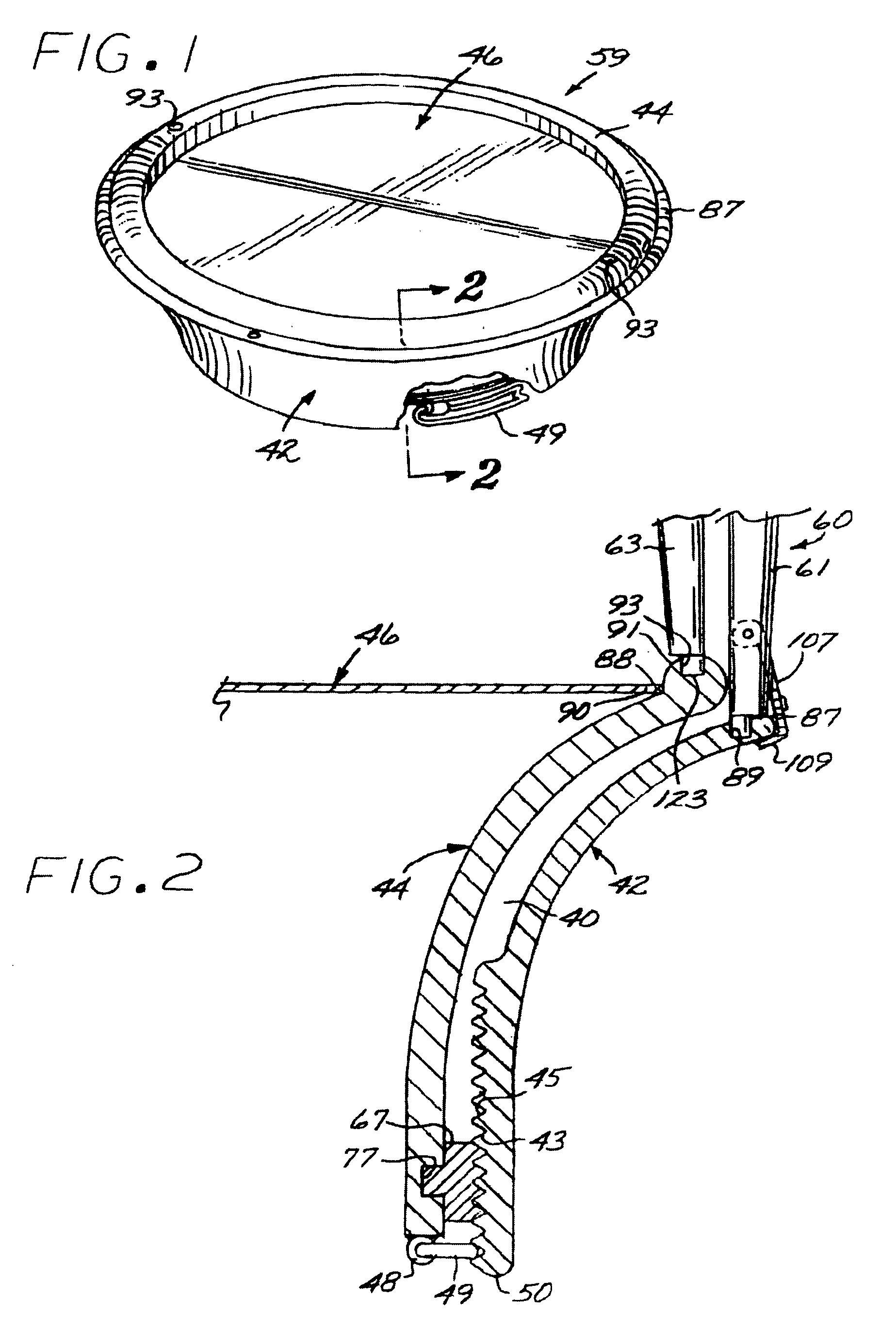
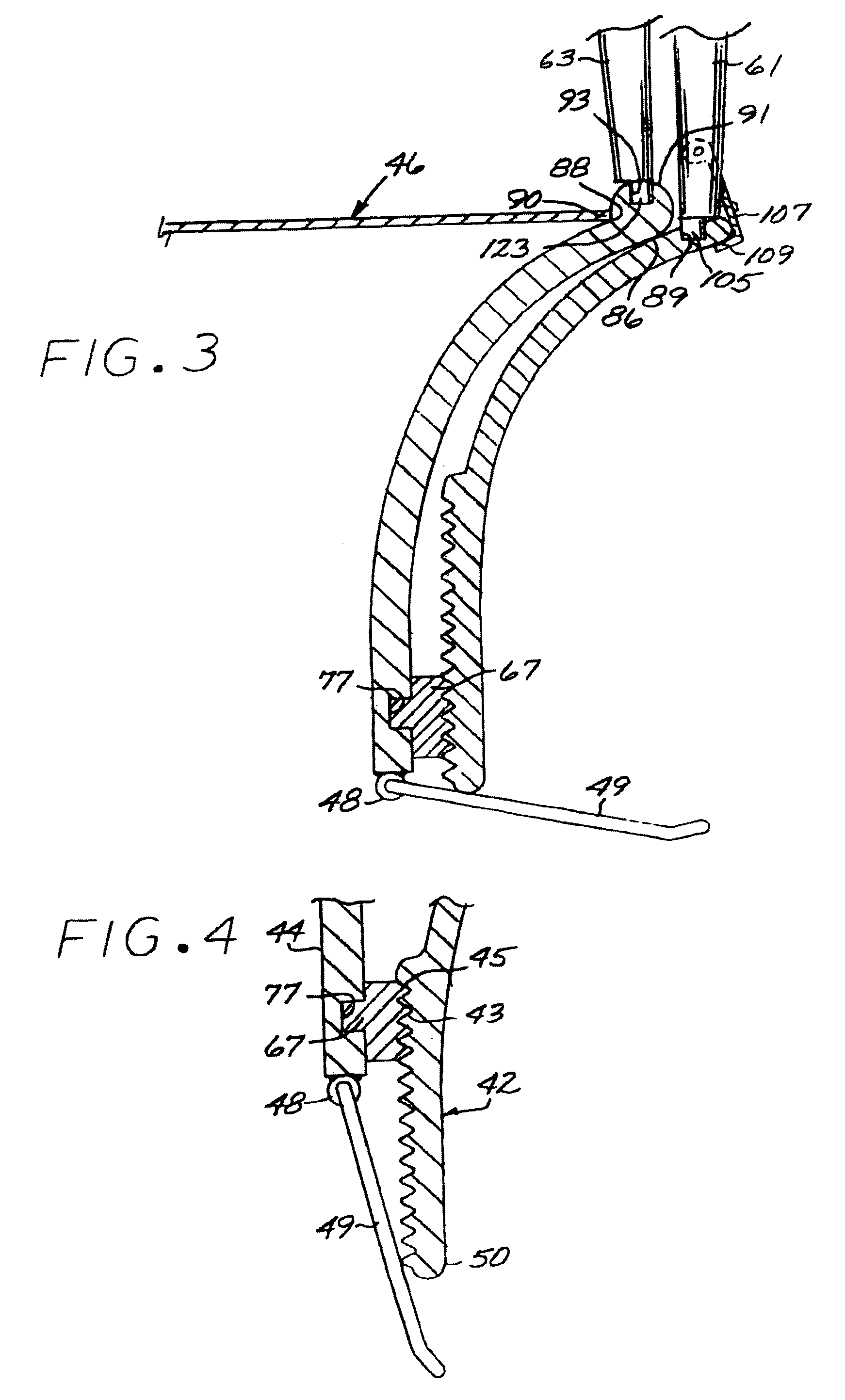
  • Heart valve annulus device and method of using same
  • Heart valve annulus device and method of using same
  • Heart valve annulus device and method of using same

Examples


second embodiment

[0059]Referring to FIGS. 11 through 13, the anchor apparatus of the present invention, shown without the prosthetic valve in place, includes, generally, a ring forming a band 131 having upper and lower ring elements 133 and 135. Interposed between the upper and lower ring elements 133 and 135 is an actuating ring, generally designated 134, configured with diamond shaped fold-inducing openings 137 spaced peripherally thereabout and configured and arranged to form therebetween axial panels 138 having their respective narrowest annular dimension on a circumferential line positioned to be, when the band is compressed axially splayed radially outwardly under the annulus shelf (FIG. 13) to cooperate in defining a retainer ring, generally designated 147. The ring may be constructed of a stressed metal covered with a biocompatible substance, or a semi-rigid plastic capable of a spring memory so that upon deployment, the anchor device will retain the axially shifted configuration without ad...

third embodiment

[0065]the prosthetic valve anchoring device of the present invention shown in FIGS. 16–18 without the prosthetic valve in place, includes a band, generally designated 201, somewhat similar to that shown in FIG. 11. The band 201 is formed with proximal and distal ring elements 203 and 205, respectively, and an actuator ring element 204 interposed between the proximal and distal elements. The distal ring element 205 is constructed with a retainer ring element, generally designated 200, having diamond shaped cut outs 202 spaced annularly apart to form said bands 206 which, when axial forces are applied, will splay radially outwardly to assume a diameter larger than that of the annulus to form an enlarged-in-diameter retainer.

[0066]Mounted about the interior of the proximal band element 203 are a plurality of rectangular latch brackets 207 configured with longitudinal passages. Corresponding elongated resilient latches, generally designated 211, are cantileverly mounted on the distal b...


PUM


Abstract

A method of implanting a universal heart valve prosthetic anchor device for receipt of a mating occluder. The anchor device includes a pair of rings axially shiftable from a retracted to a deployed position. The anchor device further formed with a plurality of flexible retaining elements received within the anchor rings and which are capable of laterally downwardly outward movement upon deployment of the rings. The deployment tool includes an elongated tubular housing mounted at its distal end with radially outwardly diverging tines for reversible engagement with the anchoring rings. A wire is telescoped through the tines for actuation of the fork thereby causing deployment of the anchoring rings. Once placed at the desired location within the heart muscle, the deployment tool is actuated causing the anchor device to shift axially thereby causing the retainers to deploy outwardly and upwardly to secure the valve anchor in place at the heart valve annulus shelf.

Description

BACKGROUND OF THE INVENTION[0001]1. Field of the Invention[0002]The present invention relates to a prosthetic heart valve anchor and a minimally invasive method for implantation.[0003]2. Description of the Prior Art[0004]It has been estimated that up to 20% of all cardiac surgeries are directly related to valve replacement or implantation of artificial valves. It is well known that a variety of medical conditions and diseases may cause damage to the heart valve which ultimately necessitates valve replacement. Certain diseases such as rheumatic fever can cause the valve orifice to shrink or pull apart. If these defects are not corrected, prolonged valvular stenosis or insufficiency may cause damage to the heart muscle and may even require complete valve replacement. Other indications, including congenital anomalies and myocardial infarction, may necessitate total valve replacement as well. [0005]When complete valve replacement is necessary, the surgeon may choose from two types of pr...

Claims


Application Information

Patent Timeline
Patent Type & Authority Patents(United States)
IPC IPC(8): A61F2/24
CPCA61F2/2403A61F2/2427A61F2/2409
Inventor MACOVIAK, JOHN A.
Owner VENTURE LENDING & LEASING IV
Why Eureka
Try Eureka