Method and apparatus for shunting induced currents in an electrical lead

a technology of induced current and electrical lead, which is applied in the direction of heart stimulators, diagnostic recording/measuring, therapy, etc., can solve the problems of discouraged use of implantable medical devices, vastly more sophisticated and complex, and capable of performing significantly more complex tasks

Inactive Publication Date: 2003-05-01
MEDTRONIC INC
View PDF17 Cites 323 Cited by
  • Summary
  • Abstract
  • Description
  • Claims
  • Application Information

AI Technical Summary

Problems solved by technology

Today's state-of-the-art implantable medical devices are vastly more sophisticated and complex than their early counterparts, and are capable of performing significantly more complex tasks.
Traditionally, however, use of these technologies have been discouraged for patients having such implanted medical devices, as the environment produced by the MRI or diathermy apparatuses is generally considered hostile to such implantable medical devices.
The dissipation of this electrical current may cause resistive heating in the tissue adjacent the electrode and may result in damage to the tissue in some cases.
Current may be limited upon detection of a predetermined condition, such as the existence of an electromagnetic field within a predetermined frequency range.

Method used


Image

  • Method and apparatus for shunting induced currents in an electrical lead
  • Method and apparatus for shunting induced currents in an electrical lead
  • Method and apparatus for shunting induced currents in an electrical lead

Examples


first embodiment

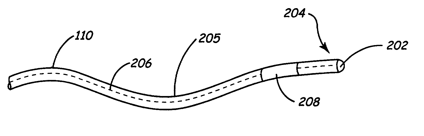
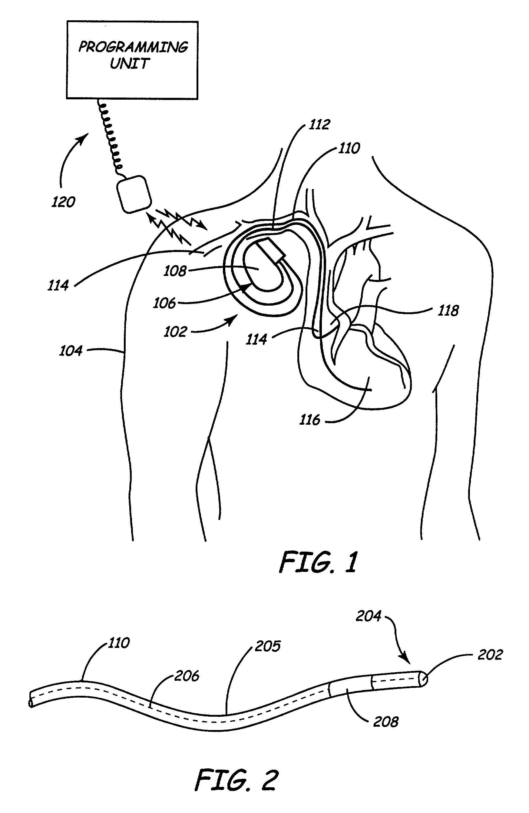
[0031] In a first embodiment, the implantable medical device 102 is a unipolar device in which the tip electrode 202 may serve as a cathode and the canister 108 may serve as an anode for pacing, stimulation, or sensing circuitry (not shown) of the implantable medical device 102. In this embodiment, as illustrated in FIGS. 2 and 3, a shunting assembly 208 includes a ring electrode 302, which is the portion of the shunting assembly 208 visible in FIG. 2. The conductor set 206 includes a tip conductor 304 that extends through the shunting assembly 208 to the tip electrode 202. The tip conductor 304 may be a continuous conductor or may be a plurality of conductors that are electrically interconnected. A capacitor 306 is electrically coupled between the tip conductor 304 and the ring electrode 302. The capacitor 306 may take the form of a single capacitive device, a plurality of capacitive devices that are electrically interconnected, or one or more capacitive devices electrically interc...

second embodiment

[0032] In a second embodiment, as illustrated in FIGS. 2 and 4, the implantable medical device 102 is a bipolar device in which the tip electrode 202 may serve as a cathode for the pacing, stimulation, or sensing circuitry (not shown) of the implantable medical device 102. In this embodiment, the shunting assembly 208 includes a ring electrode 402, which is the portion of the shunting assembly 208 visible in FIG. 2. Further, the ring electrode 402 may serve as an anode for the pacing, stimulation, or sensing circuitry of the implantable medical device 102. The conductor set 206 includes a tip conductor 404 that extends through the shunting assembly 208 to the tip electrode 202. The tip conductor 404 may be a continuous conductor or may be a plurality of conductors that are electrically interconnected. The conductor set 206 further includes a ring conductor 406 extending into the shunting assembly 208 and to the ring electrode 402. As in the tip conductor 404, the ring conductor 406 ...

third embodiment

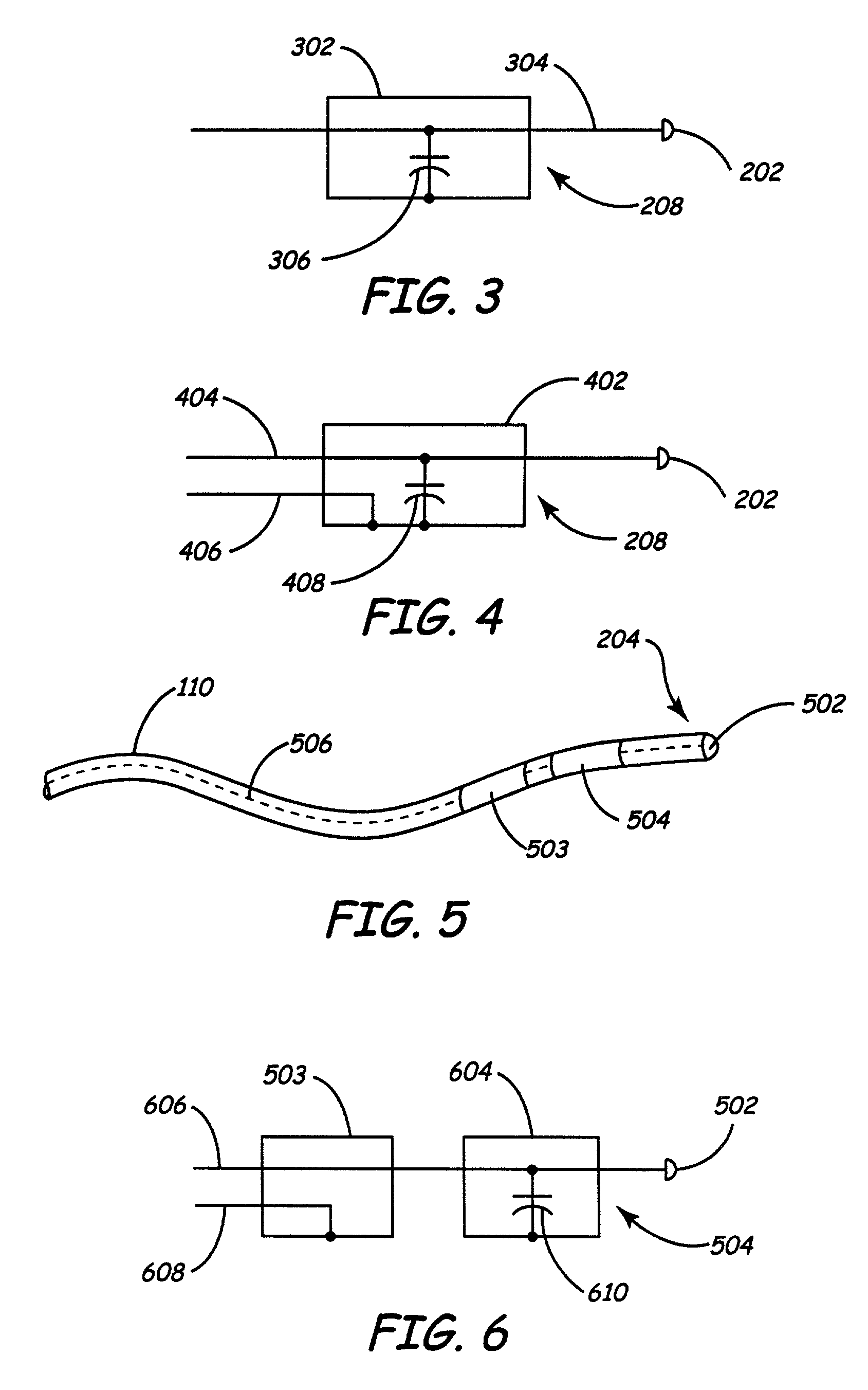
[0033] In a third embodiment, as illustrated in FIGS. 5 and 6, an implantable medical device 102 is a bipolar device in which the tip electrode 502 may serve as a cathode and a first ring electrode 503 may serve as an anode for the pacing, stimulation, or sensing circuitry (not shown) of the implantable medical device 102. In this embodiment, a shunting assembly 504 includes a second ring electrode 604, which is the portion of the shunting assembly 504 visible in FIG. 5. A conductor set 506 includes a tip conductor 606 that extends through the first ring electrode 503 and the second ring electrode 604 to the tip electrode 502. The tip conductor 606 may be a continuous conductor or may be a plurality of conductors that are electrically interconnected. The conductor set 506 further includes a ring conductor 608 extending to the first ring conductor 503. As in the tip conductor 606, the ring conductor 608 may be a continuous conductor or may be a plurality of conductors that are electr...


PUM


Abstract

An electrical lead includes an elongate body having a proximal end portion and a distal end portion, a first electrode disposed adjacent and joined to the distal end portion of the elongate body. Current flow within the first electrode is limited when a predetermined condition occurs, such as the generation of an electromagnetic field having a predetermined frequency range. The medical electrical lead may further comprise one or more second electrodes disposed adjacent the first electrode and joined to the elongate body to shunt current to body tissue when the predetermined condition occurs.

Description

[0001] This application is a continuation-in-part of application Ser. No. 09 / 999,381 filed Oct. 31, 2001 entitled "Apparatus and Method for Shunting Induced Currents in an Electrical Lead", Attorney Docket Number P9698.00.[0002] This invention relates to a method and apparatus for providing electrical stimuli to tissue or receiving electrical stimuli corresponding to one or more conditions in tissue.DESCRIPTION OF THE RELATED ART[0003] Since the introduction of the first implantable pacemakers in the 1960s, there have been considerable advancements in both the fields of electronics and medicine, such that there is presently a wide assortment of commercially available body-implantable electronic medical devices. The class of implantable medical devices (IMDs) now includes therapeutic and diagnostic devices, such as pacemakers, cardioverters, defibrillators, neural stimulators, and drug administering devices, among others. Today's state-of-the-art implantable medical devices are vastl...

Claims


Application Information

Patent Timeline
Patent Type & Authority Applications(United States)
IPC IPC(8): A61NA61N1/05A61N1/362A61N1/372A61N1/39
CPCA61N1/056A61N2001/086A61N1/3718A61N1/086
Inventor ZEIJLEMAKER, VOLKERT A.KALIN, RONHRDLICKA, GREGORY A.CHO, YONG KYUNREINKE, JAMES D.FOERSTER, LAURIE D.
Owner MEDTRONIC INC
Why Eureka
Try Eureka