DC power converter and mode-switching method

a power converter and mode-switching technology, applied in the direction of power conversion systems, process and machine control, instruments, etc., can solve the problems of increasing power loss, unsatisfactory conversion efficiency, and rendering inadequate conversion efficiency

Active Publication Date: 2011-12-27
MEDIATEK INC
View PDF4 Cites 1080 Cited by
  • Summary
  • Abstract
  • Description
  • Claims
  • Application Information

AI Technical Summary

Problems solved by technology

However, a shortcoming of the above is that, a deducted voltage Vi−V0 is consumed by the transistor Q1, rendering inadequate conversion efficiency.
In addition, the conversion efficiency gets even more unsatisfactory as a required output current gets larger.
It means that when the load of a system gets larger, power lost becomes more.
As a result, power consumed by the buck converter is not effectively reduced, and power-saving effects are rather disappointing as expected in the quiescent mode.

Method used


Image

  • DC power converter and mode-switching method
  • DC power converter and mode-switching method
  • DC power converter and mode-switching method

Examples


first embodiment

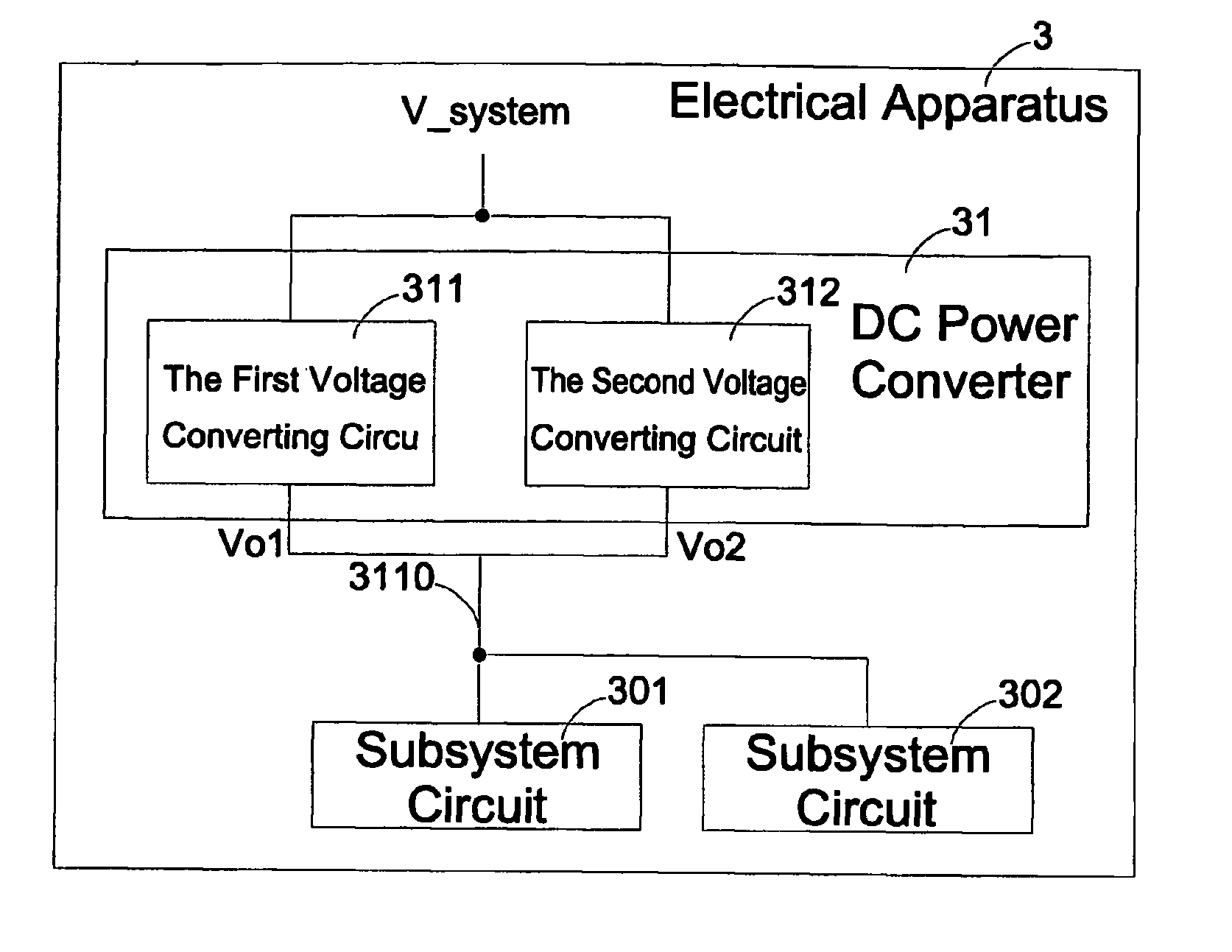
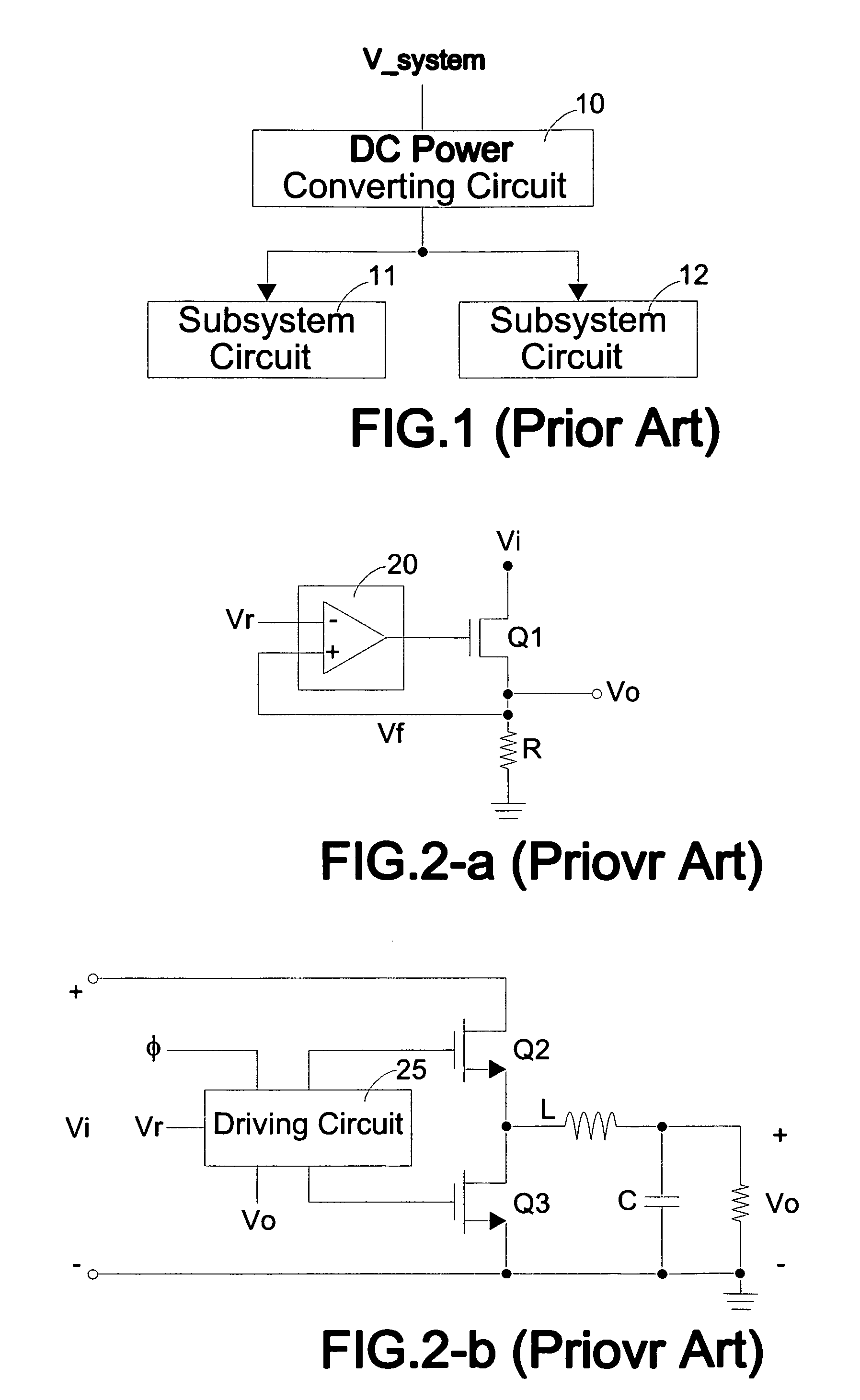
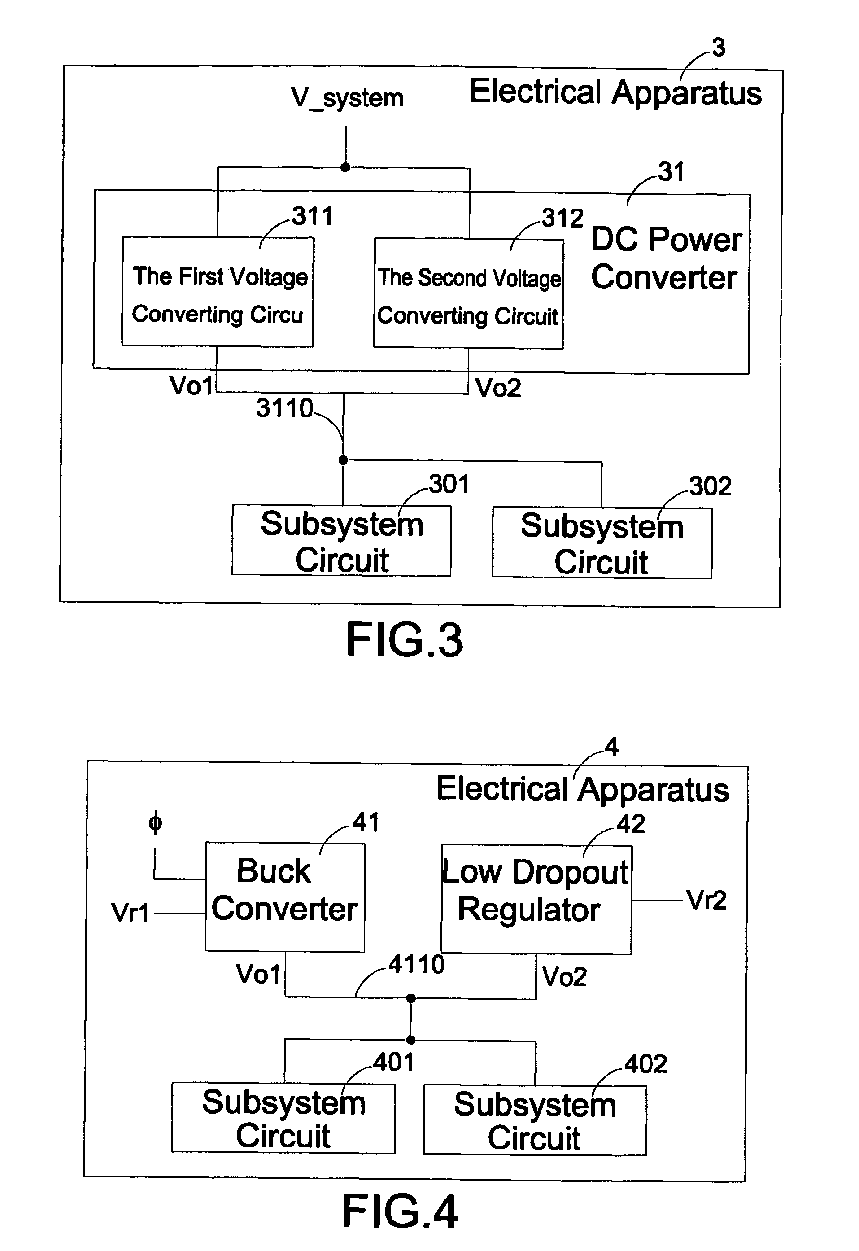
[0026]To better understand technical details of the present invention, a first embodiment according to the invention shall be illustrated with reference to FIG. 4. A buck converter 41 is implemented as the foregoing first voltage converting circuit 311, and an LDO 42 is implemented as the foregoing second voltage converting circuit 312. Circuits of the buck converter 41 and the LDO 42 are as shown in FIGS. 2(a) and 2(b). When an electronic apparatus 4 is in an active mode, the buck converter 41 is activated to output a first output voltage Vo1 at the output end 4110 for the subsystem circuits 401 and 402 based on a first reference voltage Vr1. The first output voltage Vo1 has a linear relationship with the first reference voltage Vr1. At this point, the LDO 42 detects that the voltage at the output end 4110 is larger than the second reference voltage Vr2, which is the foregoing threshold Vt, and therefore the LDO 42 becomes inactive to allow the buck converter 41 to provide the subs...

second embodiment

[0028]To more explicitly express technical details according to the invention, a preferred second embodiment shall be described with reference to FIG. 7. A first buck converter 71 is implemented as the foregoing first voltage converting circuit 311, and a second buck converter 72 is implemented as the foregoing second voltage converting circuit 312. When an electronic apparatus 7 is in an active mode, the first buck converter 71 outputs the first output voltage Vo1 at an output end 710 for subsystem circuits 701 and 702 based on the first reference voltage Vr1. The first output voltage Vo1 has a linear relationship with the first reference voltage Vr1. When a comparator 73 detects that a voltage at the output end 710 is larger than the second reference voltage Vr2, the second buck converter 72 stops operating. However, when the electronic apparatus 7 enters a quiescent mode, for that the subsystem circuits 701 and 702 no longer require large current and voltage, the first buck conve...


PUM


Abstract

A DC converter and a mode-switching method used in an electronic apparatus are included. The electronic apparatus includes a subsystem circuit. The DC power converter comprises a first voltage converting circuit electrically connected to the subsystem circuit, receiving a system voltage and a first reference voltage, and converting the system voltage to a first output voltage based on the first reference voltage; and a second voltage converting circuit electrically connected to the subsystem circuit and receiving the system voltage and a second reference voltage, and converting the system voltage to a second output voltage to the same output end of the first voltage converting circuit based on the second reference voltage; wherein the second voltage converting circuit outputs the second output voltage to the subsystem circuit when the first output voltage at the output end is smaller than a threshold.

Description

FIELD OF THE INVENTION[0001]The present invention relates to a DC power converter and a mode-switching method, and more particularly, to a DC power converter and a mode-switching method used in a portable electronic apparatus.BACKGROUND OF THE INVENTION[0002]In an electronic apparatus including multiple subsystem circuits, each of the subsystem circuits may require a different DC voltage level from another, and hence there is a need for DC power converters. Referring to FIG. 1 showing a schematic diagram of a structure of a DC power converter applied in an electronic apparatus, a system voltage supply V_system is converted via a DC power converter 10 to generate a first voltage V1 having different voltage levels to be provided to subsystem circuits 11 and 12.[0003]There are two common types of DC power converters; one is the so-called low dropout regulator (LDO). FIG. 2(a) shows a schematic diagram of an LDO circuit including a feedback control circuit 20 for an operational amplifie...

Claims


Application Information

Patent Timeline
Patent Type & Authority Patents(United States)
IPC IPC(8): G05F1/00
CPCH02J1/102H02M2001/0025H02M1/0025
Inventor WEI, CHUN KAI DERRICKCHEN, KUAN-YEUWANG, HUNG ILIN, SONG-YI
Owner MEDIATEK INC
Why Eureka
Try Eureka