Fire cover for gas stove

A gas stove and fire cover technology, which is applied in the fields of application, burner, and combustion method, can solve the problem that the gas stove fire cover does not have a flame-stabilizing function, and achieve good flame-stabilizing effects, reduced processing difficulty, and high thermal efficiency

Active Publication Date: 2016-11-23
NINGBO FOTILE KITCHEN WARE CO LTD
View PDF5 Cites 6 Cited by
  • Summary
  • Abstract
  • Description
  • Claims
  • Application Information

AI Technical Summary

Problems solved by technology

[0003] But this burner fire cover can only disassemble the cover body from the base below, and the base is provided with multiple grooves and partitions, there is a cleaning dead angle, so there is still a cleaning problem; and the gas stove fire cover No flame stabilization function

Method used


Image

  • Fire cover for gas stove
  • Fire cover for gas stove
  • Fire cover for gas stove

Examples


Embodiment 1

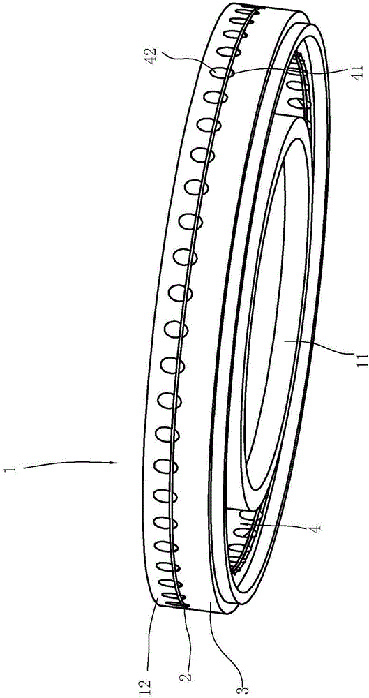
[0020] Such as Figure 1 to Figure 3 As shown, the fire cover for the gas range includes:

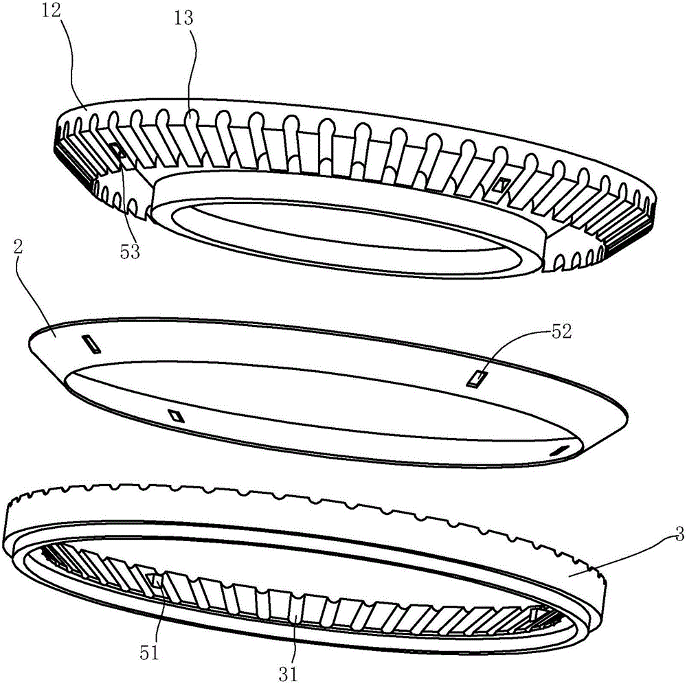
[0021] The upper cover body 1 has a ring structure. The inner ring and the outer ring of the upper cover body respectively have an inner ring wall 11 and an outer ring wall 12 extending downward, and the lower peripheral surface of the outer ring wall 12 is a conical surface with a high outside and a low inside. shape and has a plurality of radially penetrating upper grooves 13 along the circumference.

[0022] The lower cover body 3 is adapted to the outer ring wall 12 and is arranged below the outer ring wall 12. Its upper surface is also a conical surface with a high outside and a low inside, and a plurality of lower grooves 31 radially penetrating along the circumference. .

[0023] In this embodiment, the lower grooves 31 correspond to the upper grooves 13 one by one.

[0024] The spacer 2 is arranged between the upper cover body 1 and the lower cover body 3, and its upper surfa...

Embodiment 2

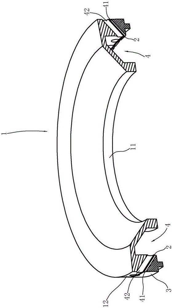
[0033] Such as Figure 4 to Figure 6 As shown, in the gas cooker fire cover in the present embodiment, the outer end side of the outer ring wall 12 is slightly protruding from the outer end side of the lower cover body 3, so that the stable flame flame of the lower fire hole is directly on the upper fire hole. root burning;

[0034] The cross-sectional area of ​​the upper fire hole is three times the cross-sectional area of ​​the lower fire hole;

[0035] The spacer 2 intersects with the horizontal plane at an angle of 65°; correspondingly, the tapers of the lower peripheral surface of the outer ring wall 12 and the upper surface of the lower cover 3 are both 65°.

[0036] All the other contents are the same as in Example 1.


PUM


Abstract

The invention relates to a fire cover for a gas stove. The fire cover is characterized by comprising an annular upper cover body, an annular separating sheet and an annular lower cover body from top to bottom. An inner ring and an outer ring of the upper cover body are provided with a downwards-extending inner ring wall and a downwards-extending outer ring wall correspondingly, wherein the lower circumferential face of the outer ring wall is in an outside-high-inside-low conical surface shape, the outer ring wall is provided with a plurality of upper grooves which are arranged in the circumferential direction and are through in the radial direction, the upper circumferential face of the separating sheet is matched with the lower circumferential face of the outer ring wall of the upper cover body, and an upper fire hole is formed through the separating sheet and the upper groove; the upper circumferential face of the lower cover body is also an outside-high-inside-low conical surface, the lower cover body is provided with a plurality of lower grooves which are arranged in the circumferential direction and are through in the radial direction, the lower circumferential face of the separating sheet is matched with the upper circumferential face of the lower cover body, and a lower fire hole is formed by the separating sheet and the lower grooves; and a gas mixing chamber is jointly defined by the inner ring wall of the upper cover body, the outer ring wall of the upper cover body, an inner circumferential wall of the separating sheet and an inner circumferential wall of the lower cover body.

Description

technical field [0001] The invention relates to a gas cooker, in particular to a fire cover for a gas cooker. Background technique [0002] Chinese invention patent application CN201510355092.X discloses "A Burner Flame Cover", which includes annular and concentrically spaced inner and outer ring walls, a cover located above the inner and outer ring walls, and the outer ring wall There are fire holes evenly distributed along the circumference of the wall of the outer ring and running through the thickness direction of the wall of the outer ring, and small fire holes spaced up and down from the fire holes. There is a partition between the wall of the inner ring and the wall of the outer ring. The plate divides the space surrounded by the inner and outer ring walls and the cover into a first cavity and a second cavity, the fire hole is located in the first cavity, and the small fire hole is located in the second cavity, and the partition plate has The hole communicates with t...

Claims


Application Information

Patent Timeline
Patent Type & Authority Applications(China)
IPC IPC(8): F23D14/76F23D14/26F24C3/12
CPCF23D14/26F23D14/76F24C3/126
Inventor 程永超李林郑军妹茅忠群诸永定
Owner NINGBO FOTILE KITCHEN WARE CO LTD
Why Eureka
Try Eureka