Locking structure for combined sports floor

A combined floor technology, which is applied in the direction of elastic floor, building structure, floor, etc., can solve the problems of arching at the splicing of sports floor, affecting the use of the field, and easy release of the pin buckle, so as to avoid accidental injury, Avoid arching or deformation, easy installation and removal

Inactive Publication Date: 2016-12-07
杭州格林康体科技有限公司
View PDF8 Cites 3 Cited by
  • Summary
  • Abstract
  • Description
  • Claims
  • Application Information

AI Technical Summary

Problems solved by technology

[0004] In the lock structure of this type of sports floor, after the male buckle is inserted into the female buckle, the edge of the male buckle is clamped at the bottom of the edge of the square splicing unit, such as figure 2 As shown, the stretching direction of the male buckle along the mouth is parallel to the stretching direction of the edge of the square splicing unit, so when this type of sports floor is subjected to a large pulling force, the male buckle is easy to disengage, and the reliability of the connection needs to be improved; and, this kind of sports floor The locking structure is a rigid connection. In hot or cold seasons, thermal expansion and contraction will cause the joints of the sports floor to arch or deform, which will affect the use of the venue; the above problems have yet to be resolved

Method used


Image

  • Locking structure for combined sports floor
  • Locking structure for combined sports floor
  • Locking structure for combined sports floor

Examples


Embodiment Construction

[0027] The present invention will be further described below in conjunction with the accompanying drawings, but the present invention is not limited to the following examples.

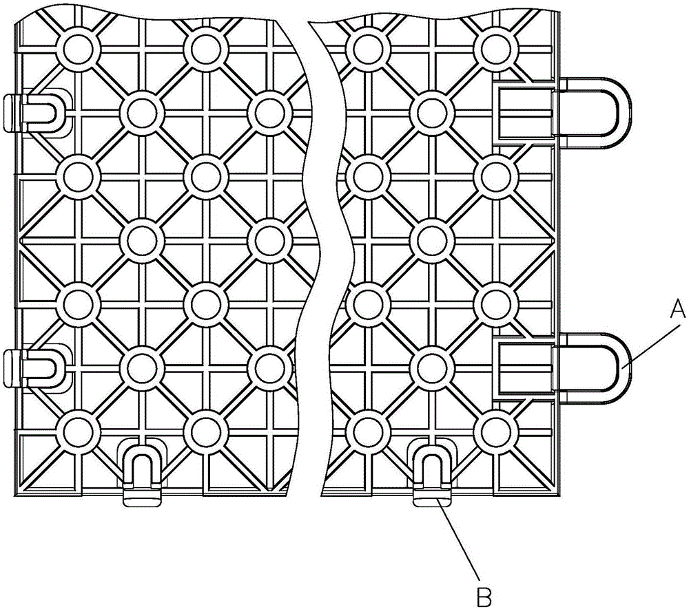
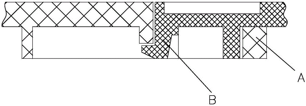
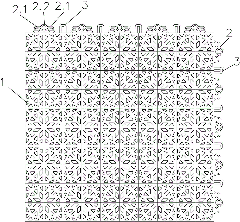
[0028] Such as image 3 , Figure 4 As shown, the locking structure of a combined sports floor according to the present invention includes two sets of female snaps 2 and two sets of male snaps, the two sets of female snaps are arranged on the lower side of two adjacent sides of the sports floor 1, and Protruding toward the outside of the sports floor, two sets of male buckles are arranged on the bottom surfaces of the other two adjacent sides and correspond to the positions of the female buckles. The arrangement above is similar to the prior art.

[0029] In the present invention, each male buckle includes a positioning post 4 arranged vertically downward, such as Figure 5 , Figure 6 As shown, the positioning column matches the inner hole 2.3 of the positioning sleeve 2.2 of the female button 2, ...


PUM


Abstract

The invention relates to a locking structure for a combined sports floor, and aims to provide the locking structure which can adapt to changes in temperature, can avoid deformation at splicing positions, and has the characteristics of reliable connection, easy installation and maintenance, simple structure and the like. According to the technical scheme, the locking structure for the combined sports floor comprises two groups of female buckles and two groups of male buckles; the two groups of female buckles are arranged on the lower sides of the two adjacent sides of the sports floor and extend toward the outer side of the sports floor; the two groups of male buckles are arranged on the bottom surfaces of the other two adjacent sides and correspond to the female buckle positions; each female buckle comprises a vertically arranged locating sleeve and elastic connecting parts symmetrically arranged on two sides of the locating sleeve; the locating sleeve is integrally connected with the edge of the sports floor through the elastic collecting parts; each male buckle comprises a vertically downwardly arranged locating column; the locating column is matched with an inner hole of the locating sleeve; a circle of bulges is arranged at the lower ends of the locating column, so as to form an inverted hook hooked at the lower part of the locating sleeve.

Description

technical field [0001] The invention relates to the technical field of suspended assembled floors, in particular to a locking structure of a combined sports floor. Background technique [0002] The combined sports floor is an application of the suspended assembled floor in the field of sports and leisure. It is the surface material of the sports field. It is composed of several square splicing units. Connected, each floor is connected with a unique lock structure, the installation is very simple, and it can be disassembled at will. [0003] The square splicing unit is divided into the bottom layer and the surface layer. The surface layer is usually divided into a grid-shaped hollow structure and a flat structure. The bottom layer is composed of several columnar or polygonal or other shaped support feet. Such as figure 1 Among the four sides of the above-mentioned square splicing unit, two adjacent sides are respectively provided with several female buttons A protruding hor...

Claims


Application Information

Patent Timeline
Patent Type & Authority Applications(China)
IPC IPC(8): E04F15/02E04F15/22
CPCE04F15/02038E04F15/22
Inventor 朱松善
Owner 杭州格林康体科技有限公司
Why Eureka
Try Eureka