
A double pole double throw radio frequency relay with auxiliary contacts
A double-pole double-throw, auxiliary contact technology, applied in relays, electromagnetic relays, electromagnetic relay details and other directions, can solve the problems of double-pole double-throw radio frequency relays that cannot monitor or indicate contact contact status, and are difficult to meet user needs.
- Summary
- Abstract
- Description
- Claims
- Application Information
AI Technical Summary
Problems solved by technology
Method used
Image

Examples
Embodiment Construction
[0021] combined with Figure 1-6 An embodiment of the present invention is described.
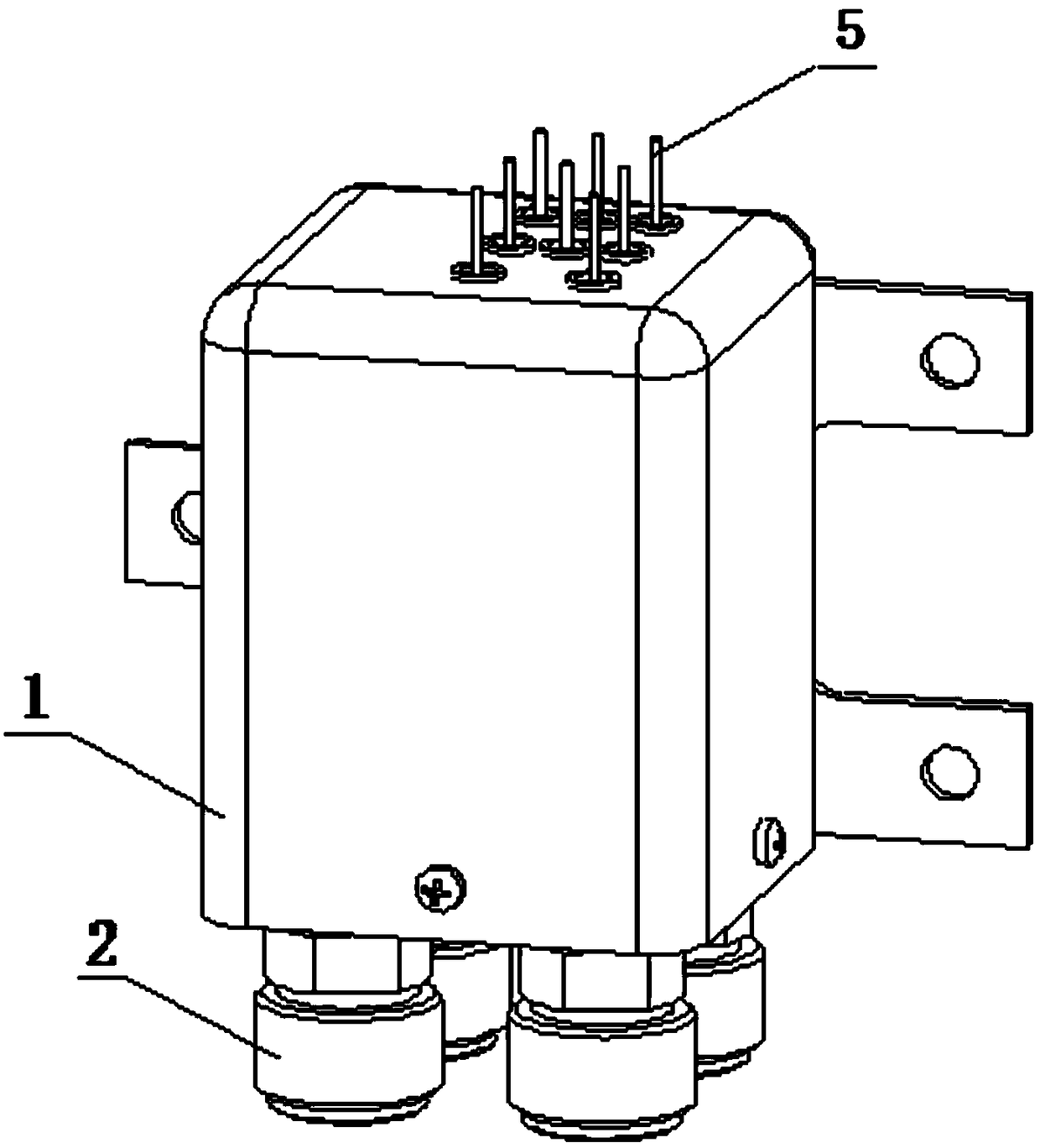
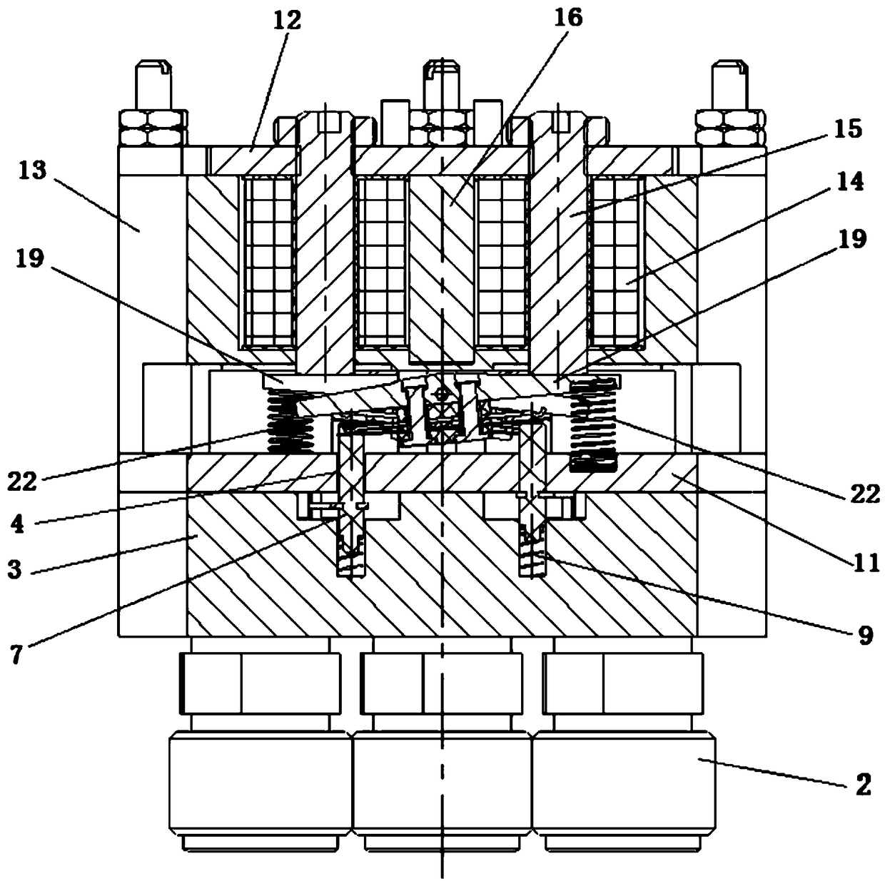
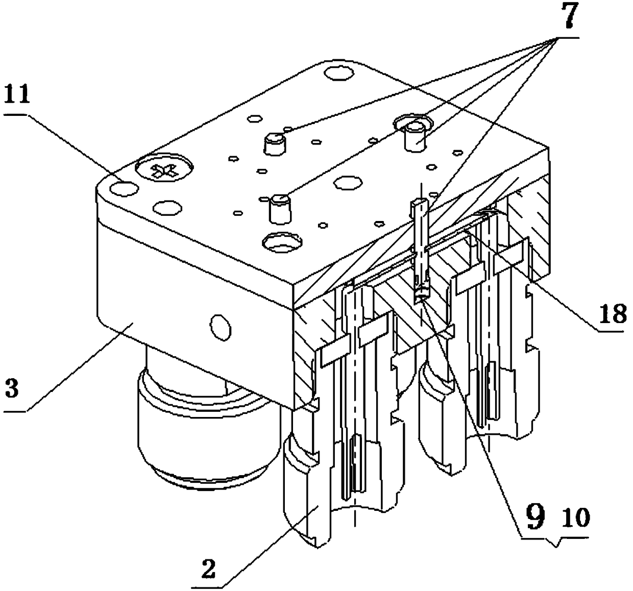
[0022] A double-pole double-throw radio frequency relay with auxiliary contacts, including a base 3 and a cover 1 fixed above the base 3, and four radio frequency output terminals 2 are fixed below the base 3, and eight are fixed above the cover 1 Input terminal 5. A contact system is fixed above the base 3, an electromagnetic system is fixed above the contact system, and both the contact system and the electromagnetic system are located in the cover 1; the upper end surface of the base 3 is shaped on a sub-shaped cavity 6, And the middle of the four sides of the sub-shaped cavity 6 is formed with blind holes 10; the contact system is composed of 4 springs I9 and 4 push rod assemblies 7; the lower ends of the spring I9 and push rod assemblies 7 are sequentially Inserted in the blind hole 10, the middle part of the push rod assembly 7 is horizontally connected with a moving reed 18, and th...
PUM
 Abstract
Description
Claims
Application Information