Isolation switch contact adjustment device

A technology of adjusting device and isolating switch, applied in electrical switches, electrical components, circuits, etc., can solve the problem of insufficient joint area of ​​dynamic and static contacts of outdoor isolating switches, and achieve the effect of safe and reliable live work, gentle action, and easy portability.

Active Publication Date: 2018-06-15
ZHANGJIAKOU POWER SUPPLY COMPANY OF STATE GRID JINBEI ELECTRIC POWER COMPANY +1
View PDF5 Cites 0 Cited by
  • Summary
  • Abstract
  • Description
  • Claims
  • Application Information

AI Technical Summary

Problems solved by technology

[0004] The purpose of the present invention is to provide a method for adjusting the static and dynamic contacts of an outdoor isolating switch, so as to solve the problem of insufficient combined area of ​​the static and dynamic contacts of an outdoor isolating switch

Method used


Image

  • Isolation switch contact adjustment device
  • Isolation switch contact adjustment device
  • Isolation switch contact adjustment device

Examples


Embodiment 1

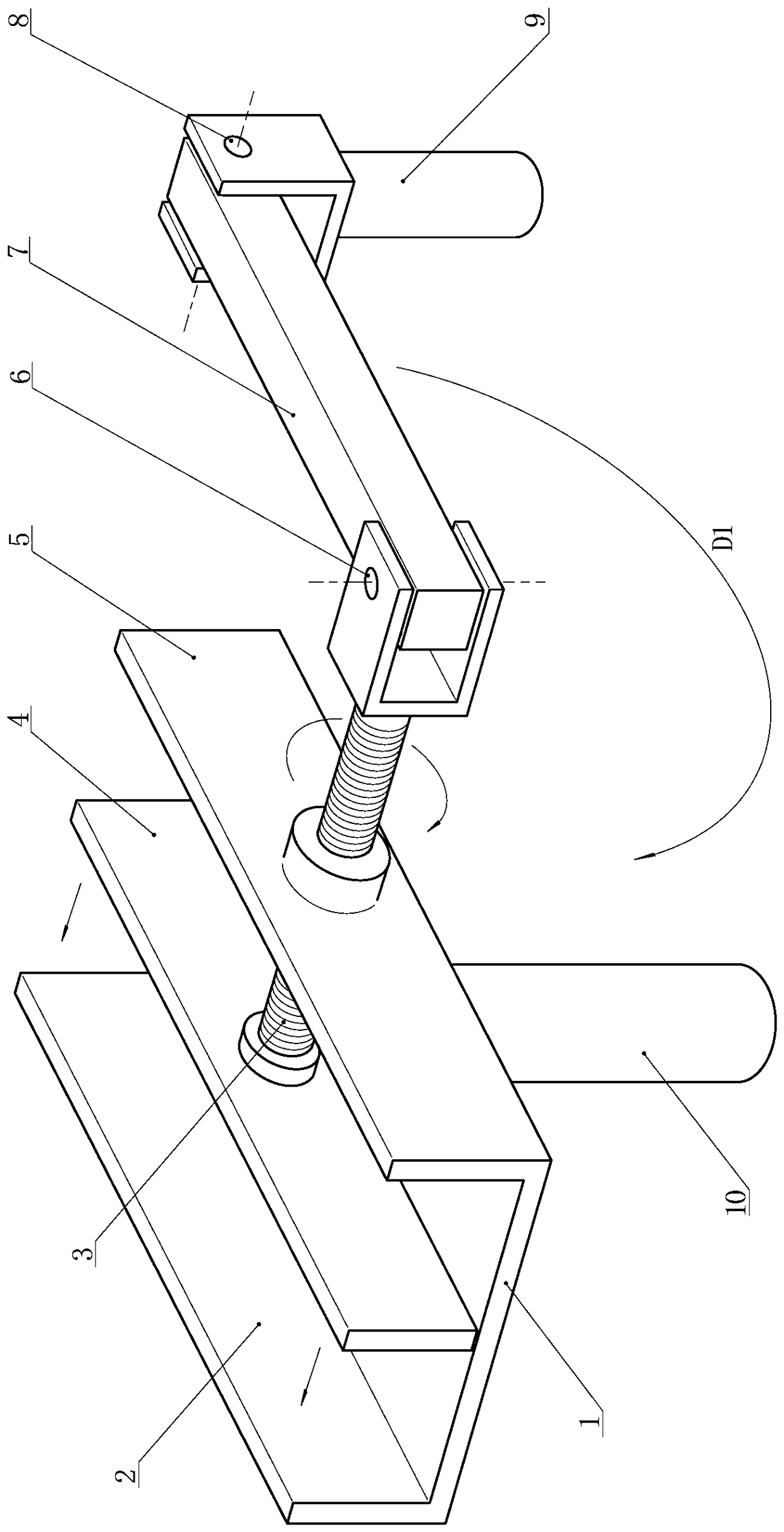
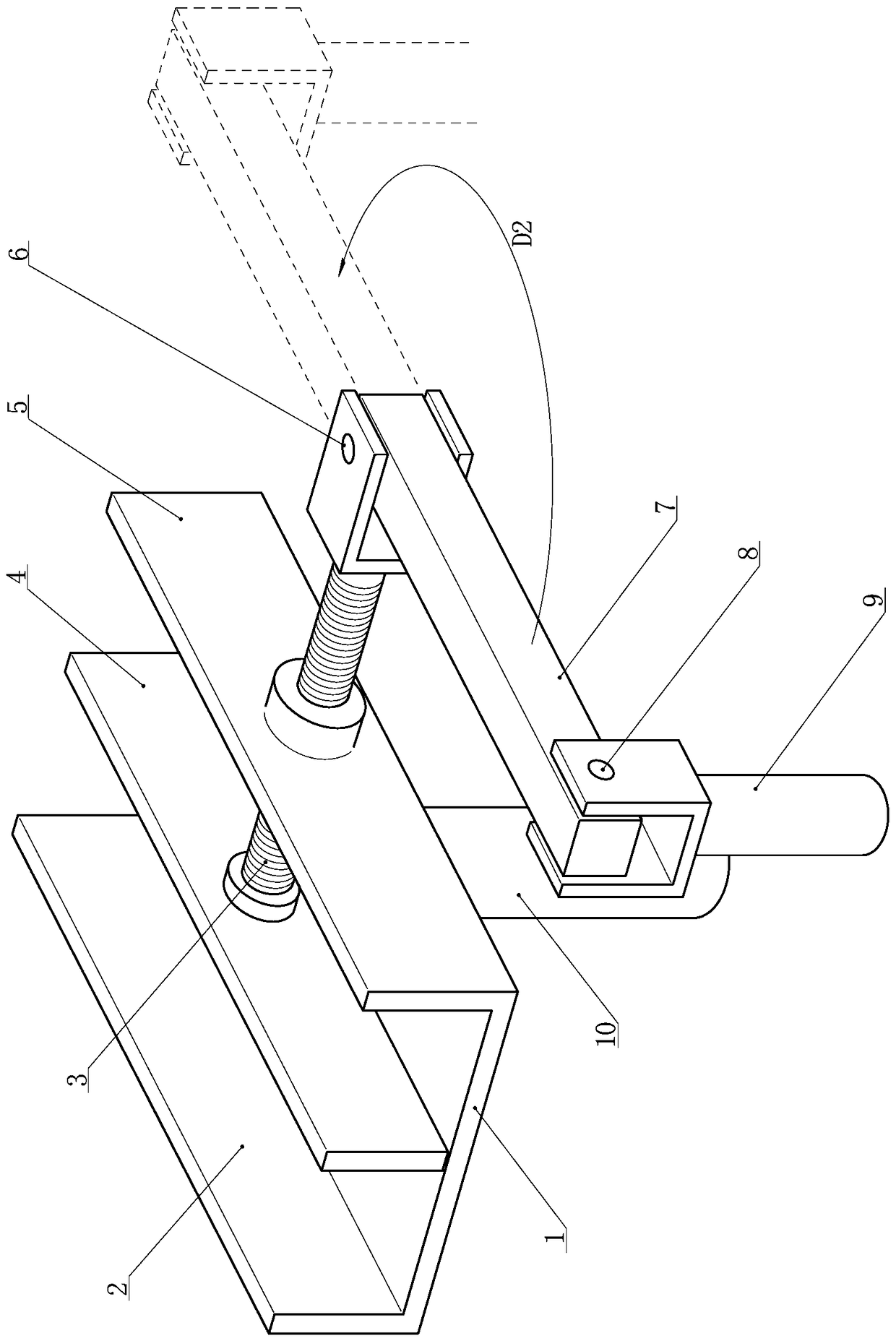
[0024] From Figure 1 ~ Figure 2 It can be seen that the present invention includes a clamping part and a transmission part;

[0025] The clamping part includes a clamping main body, a dynamic pressure plate 4 and a first connector 10 for connecting insulating rods; the clamping main body is composed of a bottom plate 1, a static pressure plate 2, and a side top plate 5; The lower edge is respectively connected with the two opposite sides of the bottom plate 1 to form a groove structure with the notch upward and both ends open; the dynamic pressure plate 4 is located in the notch of the clamping body, and is opposite to the static pressure plate 2 to form a bayonet; the first connector 10 is fixed on the lower part of the bottom plate 1 of the clamping main body.

[0026] The bottom plate 1, the static pressure plate 2, and the side top plate 5 are of an integral structure.

[0027] The transmission part includes a screw jack 3, a connecting rod 7 and a second connector 9 fo...

Embodiment 2

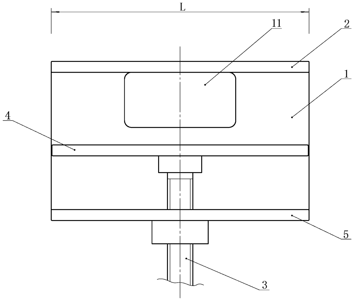
[0037] The difference between this embodiment and Embodiment 1 is that there is an observation port 11 on the side of the bottom plate 1 close to the static pressure plate 2, see image 3 , During the adjustment process of the isolating switch contacts, the staff is located below it and can observe the combination of the moving and static contacts at any time through the observation port 11. The lengths of the dynamic and static pressure plates are both 30cm; the end of the screw ejector rod located in the groove of the clamping main body is provided with a shoulder, and the shoulder is rotatably matched with the deck on the dynamic pressure plate.

[0038] Other technical features of this embodiment are the same as those of Embodiment 1.


PUM


Abstract

The invention relates to an outdoor isolation switch contact adjustment tool, in particular to an isolation switch contact adjustment device. When an isolation switch contact is switched on in place, a contact is knocked to be switched on through repeatedly breaking and closing by a constructor or by using an insulation rod to cause contact damage. The tool for adjusting the contact after the isolation switch is switched on, provided by the invention, comprises a clamping part and a transmission part, wherein the clamping part is a groove-shaped clamping main body composed of a bottom plate, a static press plate and a side top plate, a movable press plate is arranged in a groove, a first connector is fixedly arranged at a lower part of the bottom plate, a spiral top rod of the transmission part is matched with the side top plate through a thread, one end of the spiral top rod is rotatably matched with the movable press plate, the other end of the spiral top rod is hinged with a connection rod by a rotation shaft A, the other end of the connection rod is hinged with a second connector by a rotation shaft B, and the rotation shaft A is perpendicular to the rotation shaft B. The tool has the advantages that a worker stands on the ground and can operate, the tool is safe, reliable, safe and rapid and is gentle in action, and the contact cannot be damaged.

Description

technical field [0001] The invention relates to an adjustment tool for an outdoor isolating switch contact, in particular to an adjusting device for an isolating switch contact. Background technique [0002] The isolating switch, commonly known as the knife switch, is a large amount of power equipment in the power system, such as a 10kv isolating knife switch, and its contact body structure is as follows Figure 4 As shown, the moving and static contacts are combined in a horizontal insertion type, and the moving contact 13 is horizontally screwed into the static contact 12 under the control of the operating mechanism at the lower part of the knife switch. conduction; after the switch is closed, the moving and static contacts (two conductive arms or connecting plates) should be kept in a straight line, but in actual operation, due to insufficient closing force of the knife switch, the contacts are not closed in place, and the knife switch The one-sided contact of the contac...

Claims


Application Information

Patent Timeline
Patent Type & Authority Patents(China)
IPC IPC(8): H01H11/04
CPCH01H11/04
Inventor 王新新武志勇王利东唐劲辉王鹏蔡涌琛张磊
Owner ZHANGJIAKOU POWER SUPPLY COMPANY OF STATE GRID JINBEI ELECTRIC POWER COMPANY
Why Eureka
Try Eureka