Micro switch

A technology of micro switches and switches, which is applied in the direction of electric switches, electrical components, circuits, etc., can solve the problems of personnel injury, mechanical damage, property loss, etc., and achieve the effect of avoiding improper contact of wires

Active Publication Date: 2017-02-01
ZHEJIANG CLION RELAY
View PDF4 Cites 2 Cited by
  • Summary
  • Abstract
  • Description
  • Claims
  • Application Information

AI Technical Summary

Problems solved by technology

However, when the equipment used has mechanical failure, mechanical damage, or impact, if the switch is not in a safe

Method used


Image

  • Micro switch
  • Micro switch
  • Micro switch

Examples


Embodiment Construction

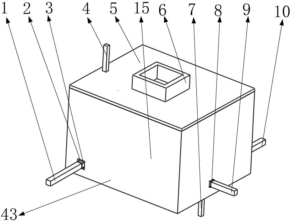
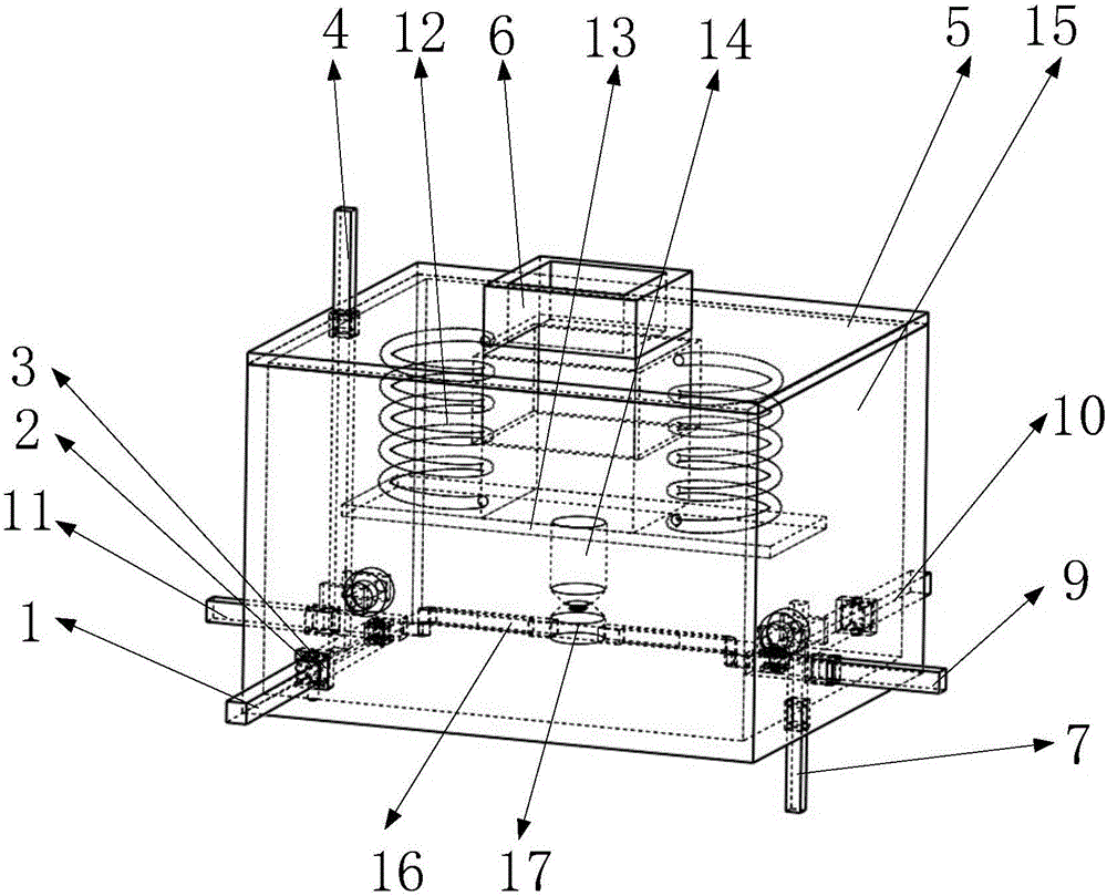
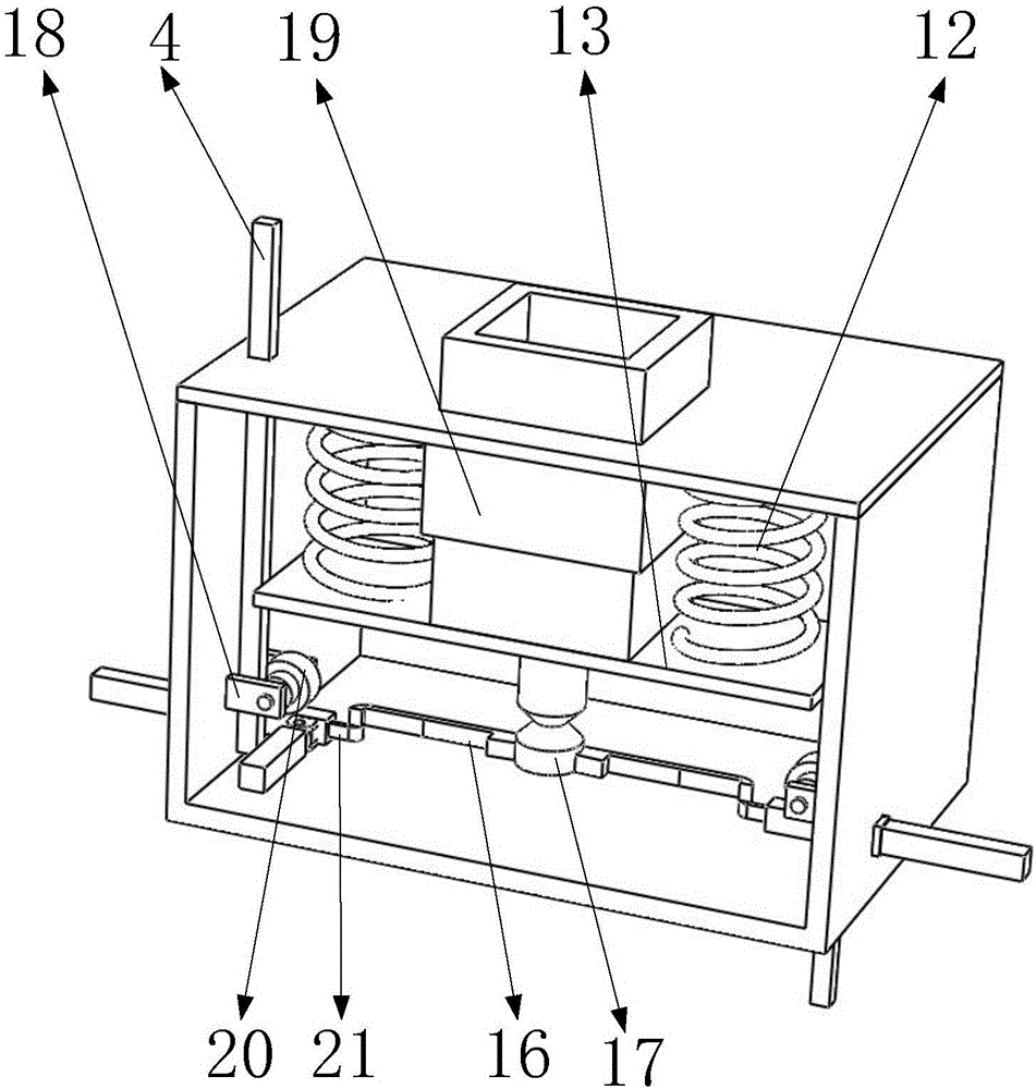
[0039] like Figure 12 , 13 , 15, it includes the first guide piece 35, the second guide piece 36, the switch housing 37, the button sliding sleeve 38, the button 39, the switch cover plate 40, the third guide piece 41, the switch bottom plate 42, the trigger mechanism 43 , the third guide block 44, the first slide bar 45, the tension spring 46, the first tension spring support 47, the floating rod 48, the trigger lever hole 49, the dial block 50, the second guide block 51, the first energy accumulation spring 52. Sliding ring limit support 53, sliding ring 54, second accumulated energy spring 55, inner column 56, limit support circular arc surface 57, electric variable slider slope 58, horizontal plate 59, electric variable slider 60, the first Four guide blocks 61, the second extension spring support 62, the fourth guide block 61, the first bar 1, the second bar 4, the third bar 7, the fourth bar 9, the fifth bar 10, the sixth bar 11, the first bar Five-bar reserved groove...


PUM


Abstract

The invention belongs to the technical field of a switch, and particularly relates to a micro switch. The micro switch comprises conductive sheets, a button, a triggering mechanism, rods, a compression spring, an extension spring, and an energy accumulation spring, wherein the first conductive sheet, the second conductive sheet, the third conductive sheet and the fourth conducive sheet are externally connected with four electric wires; the electric wire connected with the fourth conductive sheet is a safe circuit; the circuits connected with the second conductive sheet and the third conductive sheet are working circuits; the circuit connected with the first conductive sheet is a source circuit; by pressing the button, a floating rod can be triggered to switch on the second conductive sheet and the third conductive sheet through the energy accumulation of the energy accumulation spring to realize the effect of the micro switch; in addition, the triggering mechanism is added to the switch shell; the triggering mechanism is equipped with six rods; when the six rods are stressed, it is known as that the micro switch or equipment equipped provided with the micro switch is damaged or suffers from strike according to design; at the moment, the triggering mechanism is triggered to enable the floating rod to be in contact with a power transformation sliding block; and through the connection between the fourth conducive sheet and the safe circuit, fire or other power utilization accidents caused by improper electric wire contact can be avoided.

Description

[0001] Technical field [0002] The invention belongs to the technical field of switches, in particular to a micro switch. Background technique [0003] At present, micro switches have broad application prospects in various industries such as mouse, automobile, aircraft, control and detection. First of all, the function of opening and closing the wire or line selection is realized under small displacement. In addition, the micro switch is used as a detection element. On the detected device, after the operation of the device triggers the button of the micro switch, a certain function is realized. . However, when the equipment used has mechanical failure, mechanical damage, or impact, if the switch is not in a safe connection mode in time, short circuit or other dangers will often occur, resulting in personal injury and property loss. The invention designs a device that can detect the status of the switch, and then connect the switch to a safety circuit in an emergency, thereb...

Claims


Application Information

Patent Timeline
IPC IPC(8): H01H13/14H01H13/02
CPCH01H13/02H01H13/14
Inventor 张彭春郑昱张锐锐
Owner ZHEJIANG CLION RELAY
Why Eureka
Try Eureka