Magnetic levitation train and forced steering mechanism thereof

A force-oriented, car body technology, applied in electric vehicles, vehicle components, electric traction, etc., can solve the problems of large vertical deflection, equipment collision, and equipment cannot be arranged, so as to achieve small vertical installation space and reduced vertical deflection. , the effect of reducing the risk of interference

Active Publication Date: 2017-03-08
ZHUZHOU ELECTRIC LOCOMOTIVE CO
View PDF7 Cites 5 Cited by
  • Summary
  • Abstract
  • Description
  • Claims
  • Application Information

AI Technical Summary

Problems solved by technology

[0007] The present invention aims to provide a maglev train and its forced guiding mechanism, which can completely solve the problems that the equipment cannot be arranged and collides with the equipment due to the excessive vertical deflection at the central position of the ultra-slender longitudinal tie rod

Method used


Image

  • Magnetic levitation train and forced steering mechanism thereof
  • Magnetic levitation train and forced steering mechanism thereof
  • Magnetic levitation train and forced steering mechanism thereof

Examples


Embodiment Construction

[0041] The present invention will be described in detail below with reference to the accompanying drawings and examples. It should be noted that, in the case of no conflict, the embodiments of the present invention and the features in the embodiments can be combined with each other. For the convenience of description, if the words "up", "down", "left" and "right" appear in the following, it only means that the directions of up, down, left and right are consistent with the drawings themselves, and do not limit the structure.

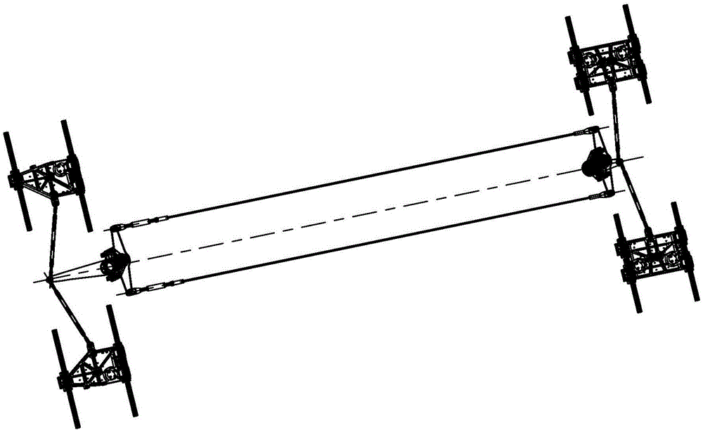
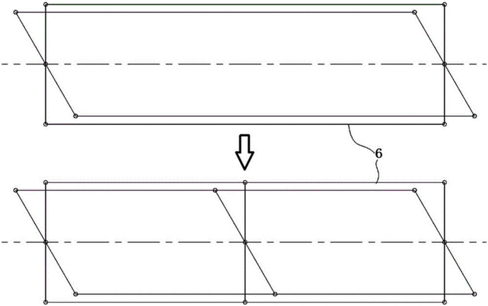
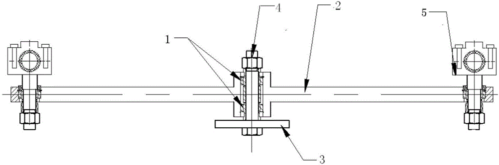
[0042] A mechanically forced guiding mechanism, such as figure 2 , 3As shown, a set of supporting arm structure is added in the middle of the two sets of rotating arms of the existing forced guide mechanism, and the longitudinal position can be adjusted to a certain extent; Certain adjustments may be made. In this embodiment, the pull rod 6 is a steel pipe.

[0043] The main function of the support arm structure is: it is equivalent to adding a suppo...


PUM


Abstract

The invention discloses a magnetic levitation train and a forced steering mechanism thereof. The forced steering mechanism comprises two rotary arms and two draw bars. The draw bars are longitudinally arranged; the draw bars are hinged to the rotary arms, each rotary arm can rotate around a mounting seat fixed onto a train body to form a movable parallelogram frame structure. The forced steering mechanism is structurally characterized in that the middles of the two draw bars are connected with each other by a support arm structure, so that each parallelogram frame structure can be decomposed into at least two parallelogram frame structures, a rotary shaft is arranged in the middle of the support arm structure, and the top of the rotary shaft is used for being connected with the train body. The magnetic levitation train and the forced steering mechanism have the advantage that the problems of incapability of arranging equipment and collision between existing super-slender longitudinal draw bars and the equipment due to the fact that the centers of the existing super-slender longitudinal draw bars are excessively high in vertical deflection can be thoroughly solved.

Description

technical field [0001] The invention relates to a maglev train and its forced guiding mechanism, which belongs to the field of rail transit vehicles and is especially suitable for maglev trains. Background technique [0002] The main purpose of installing the forced guiding mechanism on the maglev train is: when the end sliding platform mechanism enters the curve, the middle sliding platform device is forced to arrange radially along the curve through the action of the forcing guiding mechanism, so as to ensure that the vehicle passes through the curve smoothly. Existing mechanical force-guided mechanisms such as figure 1 As shown, the main structure includes 2 sets of rotating arms, 2 sets of longitudinal tie rods (steel pipe or wire rope) and 4 sets of transverse tie rods. The longitudinal tie rods are connected with the pivoting arms through hinge points, and the pivoting arms can rotate around the mounting seats fixed on the vehicle body, thus forming a movable parallel...

Claims


Application Information

Patent Timeline
IPC IPC(8): B60L13/04
CPCB60L13/04
Inventor 李茂春李小燕陈喜红陶功安晋军辉李冠军汪林峰贺世忠朱向阳何永川孙志明谭云周鹤
Owner ZHUZHOU ELECTRIC LOCOMOTIVE CO
Why Eureka
Try Eureka