AI technical title is built by Patsnap AI team. It summarizes the technical point description of the patent document.
A display control method and display control technology, applied in the direction of digital output to display equipment, instruments, electrical digital data processing, etc., can solve the problem of high display error rate
Active Publication Date: 2017-03-15
HANGZHOU HIKVISION DIGITAL TECH
View PDF5 Cites 5 Cited by
Summary
Abstract
Description
Claims
Application Information
AI Technical Summary
This helps you quickly interpret patents by identifying the three key elements:
Problems solved by technology
Method used
Benefits of technology
Problems solved by technology
[0005] Embodiments of the present invention provide a display control method and device to at least solve the technical problem of high display error rate caused by simultaneously displaying data to be displayed on multiple physical display walls on the same display interface
Method used
Image
Click on the blue label to locate the original text in one second.
Reading with bidirectional positioning of images and text.
Examples
Embodiment 1
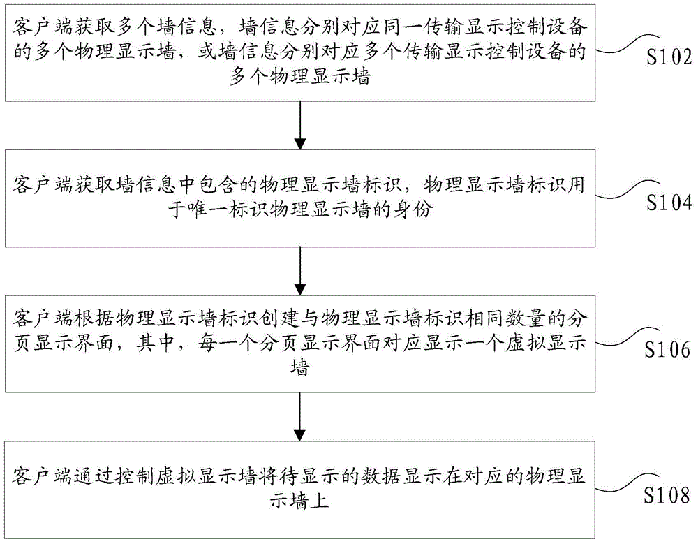
[0028] According to an embodiment of the present invention, a display control method is provided, such as figure 1 As shown, the method includes the following steps:
[0029] S102. The client acquires multiple wall information, where the wall information respectively corresponds to multiple physical display walls of the same transmission display control device, or the wall information respectively corresponds to multiple physical display walls of multiple transmission display control devices;
[0030] S104, the client acquires the physical display wall identifier contained in the wall information, where the physical display wall identifier is used to uniquely identify the identity of the physical display wall;
[0031]S106. The client creates, according to the physical display wall identifier, the same number of paging display interfaces as the physical display wall identifiers, wherein each paging display interface corresponds to displaying a virtual display wall;
[0032] S...
Embodiment 2
[0077] According to an embodiment of the present invention, a display control device is provided, such as Image 6 As shown, the device includes:
[0078] 1) The first acquiring unit 602 is configured to acquire multiple wall information, where the wall information respectively corresponds to multiple physical display walls of the same transmission display control device, or the wall information respectively corresponds to multiple physical display walls of multiple transmission display control devices;
[0079] 2) The second acquiring unit 604 is configured to acquire the physical display wall identifier included in the wall information, and the physical display wall identifier is used to uniquely identify the identity of the physical display wall;
[0080] 3) The creating unit 606 is configured to create, according to the physical display wall identifier, the same number of paged display interfaces as the physical display wall identifier, wherein each paged display interface...
PUM
Abstract
The invention discloses a display control method and device. The method comprises steps that a client obtains multiple pieces of wall information corresponding to multiple physical display walls of the same display control device respectively or corresponding to multiple physical display walls of multiple transmission display control devices respectively; the client obtains physical display wall identifiers contained in the wall information, wherein the physical display wall identifiers are used for only identifying identities of the physical display walls; the client establishes the same number of paging display interfaces as the physical display wall identifiers based on the physical display wall identifiers, wherein each paging display interface correspondingly displays one virtual display wall; and the client displays to-be-displayed data on corresponding physical display walls by controlling the virtual display walls. The technical problem that the display error rate is high when to-be-displayed data on the multiple physical display walls are displayed on the same display interface is solved.
Description
technical field [0001] The present invention relates to the display field, in particular, to a display control method and device. Background technique [0002] Nowadays, more and more occasions begin to use the TV wall to display data. Currently, for the TV wall, the commonly used control method is to control through a display control device corresponding to the TV wall, and display the data to be displayed on the TV. corresponding to the wall. However, in field applications, it is often necessary to add multiple display control devices, such as a video integrated platform and a decoder device, so that different display control devices need to display data on different TV walls at the same time. The virtual display wall of the same client to realize the control of the data display of the TV wall. That is to say, when the client controls different transmission control devices to display data on the corresponding TV wall through the virtual display wall, display conflicts ar...
Claims
Application Information
Patent Timeline
Application Date:The date an application was filed.
Publication Date:The date a patent or application was officially published.
First Publication Date:The earliest publication date of a patent with the same application number.
Issue Date:Publication date of the patent grant document.
PCT Entry Date:The Entry date of PCT National Phase.
Estimated Expiry Date:The statutory expiry date of a patent right according to the Patent Law, and it is the longest term of protection that the patent right can achieve without the termination of the patent right due to other reasons(Term extension factor has been taken into account ).
Invalid Date:Actual expiry date is based on effective date or publication date of legal transaction data of invalid patent.

