The Method of Preventing Axlebox Bearing from Abrasion by Adjusting the Joint Parameters of the Rotary Arm and the Joint of the Rotary Arm

A technology of axle box bearings and rotating arms, which is applied in the field of locomotive parts manufacturing, and can solve problems such as axle bearing wear

Active Publication Date: 2019-01-22
ZHUZHOU TIMES RUIWEI ANTI VIBERATION EQUIP LTD
View PDF10 Cites 0 Cited by
  • Summary
  • Abstract
  • Description
  • Claims
  • Application Information

AI Technical Summary

Problems solved by technology

[0011] The purpose of the present invention is to propose a method for preventing or reducing the wear of the locomotive axle bearing and the joint of the joint of the joint of the joint of the joint of the joint of the joint of the joint of the joint of the joint of the joint of the joint of the joint of the joint of the joint of the joint of the joint of the joint of the joint of the joint

Method used


Image

  • The Method of Preventing Axlebox Bearing from Abrasion by Adjusting the Joint Parameters of the Rotary Arm and the Joint of the Rotary Arm
  • The Method of Preventing Axlebox Bearing from Abrasion by Adjusting the Joint Parameters of the Rotary Arm and the Joint of the Rotary Arm

Examples


Embodiment 1

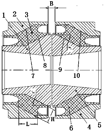
[0079] attached figure 1 and 2 A specific embodiment of the present invention is given; the joint of the rotating arm is formed by the combination of two elastic rubber parts with symmetrical structure, including the left metal outer sleeve 2 and the left metal inner sleeve 1, between the left metal outer sleeve 2 and the left metal inner sleeve 1 There is a left rubber layer 3 integrally vulcanized between the right metal outer sleeve 4 and the right metal inner sleeve 5, and a right rubber layer 6 is integrally vulcanized between the right metal outer sleeve 4 and the right metal inner sleeve 5; the left metal inner sleeve 1 and the right metal inner sleeve The inner holes of the inner sleeve 5 are tapered holes arranged opposite to each other, that is, the big head of the tapered hole is outside, and the small head of the tapered hole is close to each other on the inside; the characteristic is that the left rubber layer 3 and the right rubber layer 6 are opposite to each ot...

Embodiment 2

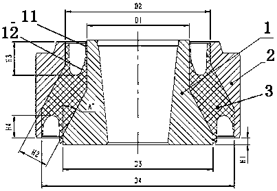
[0082] The structure of embodiment 2 is basically the same as that of embodiment 1, except that the parameters of the added rubber layer are different. The angle between the inclined surface of the rubber layer of the pivot arm node and the axis is 24~28 degrees; the length of the rubber layer is controlled at 38-45mm, left The thickness H of the rubber layer and the right rubber layer is 25-28mm; the inner diameter of the inner sleeve of the pivot arm node is set to 91~92mm, and the outer diameter is set to 129~130mm; the inner diameter of the outer sleeve is set to 129~130mm. The outer diameter is set at 171~172mm; the thickness of the rubber layer at the pivot arm node is controlled at 25-28mm.

Embodiment 3

[0084] Embodiment 3 has basically the same structure as Embodiment 1, except that the two ends of the rubber layer of the inner sleeve of the pivot arm node are dug inwards with a circle of annular grooves; wherein, the depth of the groove at the small diameter end H3 controls 15~30mm; the groove depth H4 at the end of the large diameter is controlled at 10~20mm. By digging a full circle of grooves, the radial stiffness of the boom node can be reduced, and the axial stiffness of the boom node can be improved, so that the boom The longitudinal stiffness of the nodes is controlled at 11-13KN.mm -1 , the axial stiffness is controlled at 6-8KN.mm -1 , so as to reduce the lateral load when the vehicle passes through the curve at high speed, reduce the wear of the bearing inside the axle box, and at the same time facilitate the installation without the need for empty phase.

[0085] The groove is a multi-section deep groove; wherein, the first section of the groove 11 is a single-s...


PUM

PropertyMeasurementUnit
Lengthaaaaaaaaaa
Thicknessaaaaaaaaaa
Thicknessaaaaaaaaaa

Abstract

Provided is a method for preventing axle box bearing abrasion by adjusting pivoted arm node parameters. The method is characterized in that a two-section tapered inner hole pivoted arm note composite structure is adopted, the longitudinal rigidity, axial rigidity, torsional rigidity and deflection rigidity of a pivoted arm node are changed by adjusting parameters of all aspects of the pivoted arm node, the longitudinal rigidity and the deflection rigidity of the pivoted arm node are reduced, a transverse load of a vehicle passing through a curve at a high speed is reduced, by increasing the axial rigidity, the phenomenon that the torsional rigidity of the pivoted arm node is reduced is avoided, and therefore bearing abrasion inside an axle box is reduced. Accordingly, pivoted arm type axle box positioning is adjusted by improving the longitudinal rigidity and the axial rigidity of the pivoted arm node, the transverse load of the vehicle passing through the curve at a high speed is reduced, and the bearing abrasion inside the axle box is prevented or reduced.

Description

technical field [0001] The invention relates to a method and device for adjusting the performance of locomotive parts, in particular to a method for preventing or reducing the wear of the locomotive axle box bearings by changing the performance of the locomotive pivot arm nodes and the pivot arm nodes for improving the performance of the locomotive axle box. The service life of the bearing. It belongs to the technical field of locomotive parts manufacturing. Background technique: [0002] The pivoting arm axle box positioning method is a traditional axle box positioning method, which is widely used in light rail, subway, ordinary passenger cars and high-speed EMU bogies. The so-called rotating arm type axle box positioning is that the axle box and the positioning rotating arm are combined to form a rotating arm shaft, and the axle box and the positioning pull rod are integrated to form a rotating arm structure. The positioning of the pivoting arm of the axle box is connect...

Claims


Application Information

Patent Timeline
IPC IPC(8): B61F5/30
Inventor 蒋仲三冯万盛程海涛荣继刚林胜李斌曾慧
Owner ZHUZHOU TIMES RUIWEI ANTI VIBERATION EQUIP LTD
Why Eureka
Try Eureka