
a sprinkler truck
A technology of sprinkler trucks and sprinkler boxes, applied in climate change adaptation, horticulture, botanical equipment and methods, etc., can solve the problems of not being environmentally friendly, large equipment investment, high cost, etc., to reduce manual operations, improve work efficiency, and improve The effect of automatic control rate
Patent Information
- Authority / Receiving Office
- CN · China
- Patent Type
- Patents(China)
- Current Assignee / Owner
- Publication Date
- 2018-08-03
Smart Images
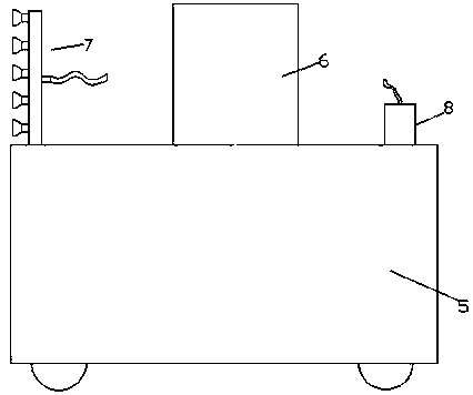
Figure 1 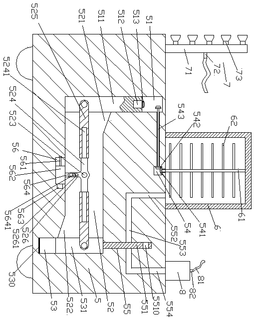
Figure 2 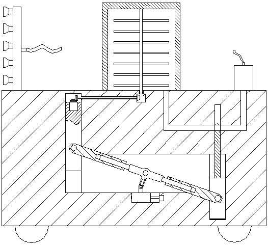
Figure 3
Abstract
Description
technical field
[0001] The invention relates to the field of sprinkler irrigation, in particular to a sprinkler irrigation vehicle. Background technique
[0002] Water resources are precious, especially in water-scarce areas where there is not enough rain. In these places, agricultural irrigation needs to be carried out in strict compliance with the principle of water conservation to avoid damage to the environment. The original extensive irrigation has long been unable to meet modern needs, and refined management has become the development direction. Among them, drip irrigation is especially water-saving, but its equipment investment is large and costly, while sprinkler irrigation is relatively low in cost and water-saving. It is driven by engine oil, which is not environmentally friendly, and the spray tanker does not have a mixing function. When it is necessary to add chemicals to the water, automatic mixing cannot be achieved, resulting in uneven concentration of the sol...
Examples
Embodiment Construction
[0021] Such as Figure 1-Figure 4 As shown, a sprinkler truck of the present invention includes a sprinkler housing 5 and a sprinkler tank 6 arranged on the top of the sprinkler tank 5, and a first cavity is arranged in the sprinkler housing 5 below the sprinkler tank 6 chamber 54, the inner top wall of the first chamber 54 is connected with a first conical wheel 541, and the top of the first conical wheel 541 is fixed with an upwardly extending section passing through the inner top wall of the first chamber 54 And the agitating shaft 61 that is transferred, the second chamber 52 extending left and right is arranged in the sprinkler housing 5 below the first chamber 54, and the extension end on the left side of the second chamber 52 communicates with a The first sliding joint cavity 51 extending upwards, the top extension section of the first sliding joint cavity 51 is located at the left relative position of the first cavity 54 , the left inner wall of the first cavity 54 is ...