

Attachment For A Handheld Appliance
A technology for accessories and appliances, which is applied in the field of accessories for hand-held appliances, and can solve problems such as uncomfortable touch
- Summary
- Abstract
- Description
- Claims
- Application Information
AI Technical Summary
Problems solved by technology
Method used
Image

Examples
Embodiment Construction
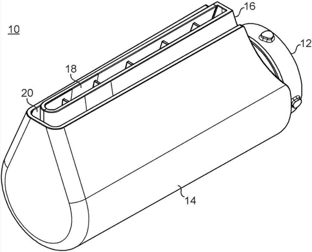
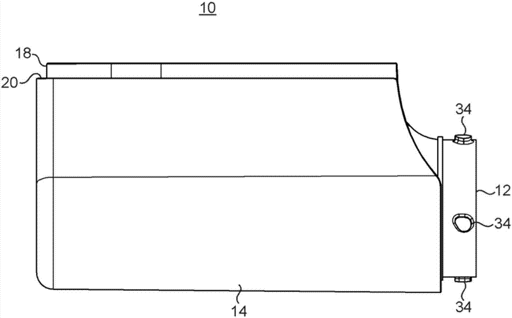
[0030] figure 1 , 3 , 4 and 5 are external views of the accessory 10. The accessory 10 includes an air inlet 12 for receiving an air flow from an air outlet end of a hot air profiling appliance or similar appliance. The air inlet is generally circular in shape to enable an airtight seal connection with the generally annular air outlet end of the hot air profiling device.
[0031] The air inlet 12 is in fluid communication with a conduit 16 . The duct 16 has an air outlet 18 which is elongated in this embodiment. The outer surface of the attachment 10 is in the form of a cold wall 14 extending partly around the duct. The air outlet 18 extends beyond the top opening 20 of the cold wall 14 .
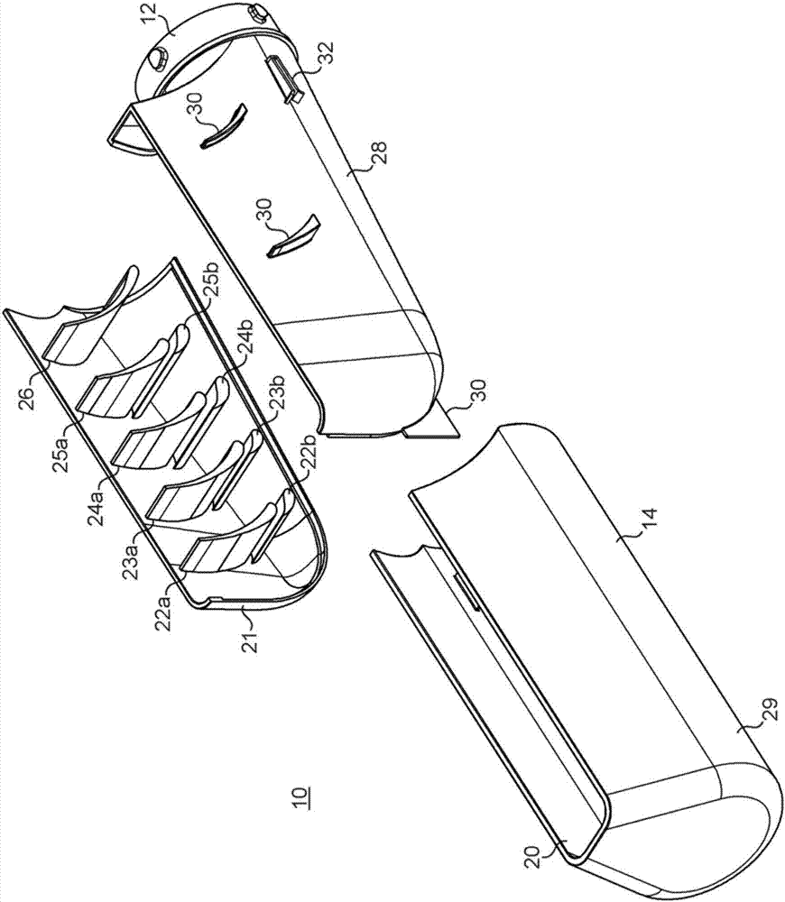
[0032] figure 2 The three parts of the attachment and their internal structure are shown.
[0033] The first portion 21 defines the first half of the duct 16 and has a plurality of fins 22 , 23 , 24 , 25 , 26 integrally molded. The second portion 28 defines the second half of the d...
PUM
 Abstract
Description
Claims
Application Information