Cable connection lantern ring type clamp convenient to use and working method thereof

A cable and ferrule technology, applied in the field of ferrule type fixtures for cable connection, can solve the problems of limited connection stability, affecting normal use, easy to loosen or fall off, etc., to achieve compact structure, good use stability, good practical effect

Inactive Publication Date: 2017-12-22
卞毓平
View PDF6 Cites 0 Cited by
  • Summary
  • Abstract
  • Description
  • Claims
  • Application Information

AI Technical Summary

Problems solved by technology

[0002] Power fittings are a relatively common structure in power cables. Power fittings in the prior art are mainly composed of a base and a pressure plate. The base and the pressure plate are evenly provided with tooth tips, and the base and the pressure plate are fixed by screws. When there are cables When the cable is put in, when the screw is tightened, the tip of the tooth will penetrate the surface insulation layer of the cable and connect with the internal conductive part. Although it can meet the general use requirements, its connection stability is relatively limited, and it will not last for a long time. It is easy to loose or fall off during use, which will affect its normal use

Method used


Image

  • Cable connection lantern ring type clamp convenient to use and working method thereof

Examples


Embodiment 1

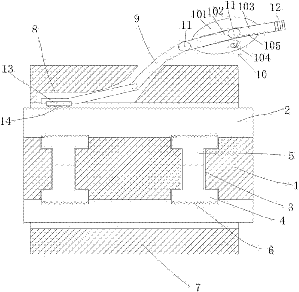
[0027] Such as figure 1 The shown convenient-to-use collar-type clamp for cable connection includes a center rod 1, at least two arc-shaped grooves 2 for placing cables on the outer side of the center rod, and The insertion cavities 3 with the same number as the arc-shaped grooves 2 are provided therein, and the inner ends of the insertion cavities 3 are communicated and the outer ends respectively extend into the arc-shaped grooves 2, and are also provided with pressing arc-shaped blocks 4 and The column insertion rod 5 fixed on the pressing arc block 4 is provided with a pressing tooth tip 6 on the arc surface of the pressing arc block 4, and the column insertion rod 5 is inserted into the The different pressing arc blocks 4 in the insertion cavity 3 are abutted by the insertion rod 5, and a collar 7 is also provided. The inner wall of the collar 7 is provided with the same number as the arc grooves 2 The strip card slot 8 is also provided with a V-shaped pressing block 9. T...

Embodiment 2

[0039] Such as figure 1 The shown convenient-to-use collar-type clamp for cable connection includes a center rod 1, at least two arc-shaped grooves 2 for placing cables on the outer side of the center rod, and The insertion cavities 3 with the same number as the arc-shaped grooves 2 are provided therein, and the inner ends of the insertion cavities 3 are communicated and the outer ends respectively extend into the arc-shaped grooves 2, and are also provided with pressing arc-shaped blocks 4 and The column insertion rod 5 fixed on the pressing arc block 4 is provided with a pressing tooth tip 6 on the arc surface of the pressing arc block 4, and the column insertion rod 5 is inserted into the The different pressing arc blocks 4 in the insertion cavity 3 are abutted by the insertion rod 5, and a collar 7 is also provided. The inner wall of the collar 7 is provided with the same number as the arc grooves 2 The strip card slot 8 is also provided with a V-shaped pressing block 9. T...

Embodiment 3

[0051] Such as figure 1 The shown convenient-to-use collar-type clamp for cable connection includes a center rod 1, at least two arc-shaped grooves 2 for placing cables on the outer side of the center rod, and The insertion cavities 3 with the same number as the arc-shaped grooves 2 are provided therein, and the inner ends of the insertion cavities 3 are communicated and the outer ends respectively extend into the arc-shaped grooves 2, and are also provided with pressing arc-shaped blocks 4 and The column insertion rod 5 fixed on the pressing arc block 4 is provided with a pressing tooth tip 6 on the arc surface of the pressing arc block 4, and the column insertion rod 5 is inserted into the The different pressing arc blocks 4 in the insertion cavity 3 are abutted by the insertion rod 5, and a collar 7 is also provided. The inner wall of the collar 7 is provided with the same number as the arc grooves 2 The strip card slot 8 is also provided with a V-shaped pressing block 9. T...


PUM


Abstract

The present invention relates to a cable connection lantern ring type clamp convenient to use and a working method thereof. The clamp comprises a central rod in which plugging cavities are arranged and arc-shaped grooves, and is also equipped with abutting arc-shaped blocks and plugging column rods fixed on the abutting arc-shaped blocks. Abutting tooth tips are arranged on the arc-shaped surfaces of the abutting arc-shaped blocks. The clamp is also equipped with a lantern ring, and the bar-shaped fastening grooves of which the number is equal to the number of the arc-shaped grooves are arranged on the inner wall of the lantern ring. The clamp is also equipped with a V-shaped briquetting, and the corner of the V-shaped briquetting is connected with the lantern ring via a rotating shaft. One end of the V-shaped briquetting is located in the bar-shaped fastening grooves of the lantern ring, and the other end is located at the outer side of the lantern ring and is connected with an adjusting mechanism via a movable shaft. The V-shaped briquetting rotates by taking the rotating shaft as the center under the action of the adjusting mechanism, so that a conductive block at the inner side end abuts against a cable. The cable connection lantern ring type clamp of the present invention is reasonable in structure setting, is convenient to use, can fix and conduct the connected cables effectively, can guarantee the usage reliability and the service life, and is good in usage stability, strong in applicability and good in practicality.

Description

Technical field [0001] The invention belongs to the technical field of power cable connection, and in particular relates to a convenient cable connection collar type clamp and a working method of the convenient cable connection collar type clamp. Background technique [0002] Power fittings are a relatively common structure in power cables. The prior art power fittings are mainly composed of a base and a pressure plate. The base and pressure plate are evenly provided with tooth tips, and the base and pressure plate are fixed by screws. When the cable is put in, while the screw is tightened, the tooth tip will penetrate the surface insulation layer of the cable and connect with the internal conductive part. Although it can meet the general needs of use, its connection stability is relatively limited, and it takes a long time. It is easy to loose or fall off during use, which will affect its normal use. [0003] Therefore, the above-mentioned problems need to be solved urgently. Su...

Claims


Application Information

Patent Timeline
Patent Type & Authority Applications(China)
IPC IPC(8): H02G1/14
CPCH02G1/14
Inventor 卞毓平
Owner 卞毓平
Why Eureka
Try Eureka