Feeding cold rolled tube slewing device

A technology of rotary device and cold-rolled pipe, applied in the direction of driving device for metal rolling mill, metal rolling, metal rolling, etc., can solve the problems of complex structure and complex structure of the driving mechanism, and achieve simple structure, low cost, Easy to install and use

Inactive Publication Date: 2018-01-16
刘园满
View PDF0 Cites 0 Cited by
  • Summary
  • Abstract
  • Description
  • Claims
  • Application Information

AI Technical Summary

Problems solved by technology

[0002] The current cold rolling mill has at least three rolls or more, and the struct

Method used


Image

  • Feeding cold rolled tube slewing device

Examples


Embodiment Construction

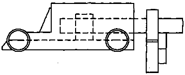
[0009] Such as figure 1 As shown, the technical solution of the present invention is: a rotary device for feeding cold-rolled pipes, including a trolley, a fixed unit, a basic unit and a dragging structure, characterized in that the output end of the basic unit is installed on the dragging structure, The fixed frame is installed on the vehicle body, the dragging structure is installed on the fixed unit, and the input end of the basic unit is connected to the output end of the power mechanism through transmission.

[0010] Finally, it should be noted that the above embodiments are only used to illustrate the technical solutions of the present invention rather than limit the protection scope of the present invention. Although the present invention has been described in detail with reference to the preferred embodiments, those of ordinary skill in the art should understand that Modifications or equivalent replacements are made to the technical solutions of the present invention w...


PUM


Abstract

The invention discloses a feeding cold rolled tube slewing device. The feeding cold rolled tube slewing device includes a trolley, a fixing unit, a basic unit, and a dragging structure; an output endof the basic unit is arranged on the dragging structure; a fixing rack is arranged on a trolley body; the dragging structure is arranged on the fixing unit; and an input end of the basic unit is drivingly connected to an output end of the power mechanism. The feeding cold rolled tube slewing device is reasonable in design, is simple in structure, is energy-saving and environment-friendly, is easyto produce, is low in cost, is easy to install and use, will not affect design, facilitates standardization and industrial production.

Description

technical field [0001] The invention belongs to the field of cold-rolled pipe mills, in particular to a rotary device for feeding cold-rolled pipes. Background technique [0002] The current cold-rolled pipe mill has at least three rolls or more, and the structure is complicated, especially the structure of the driving mechanism is quite complicated. Contents of the invention [0003] Aiming at the deficiencies in the prior art, the object of the present invention is to provide a rotary device for feeding cold-rolled tubes. [0004] The technical solution of the present invention is: a rotary device for feeding cold-rolled pipes, including a trolley, a fixed unit, a basic unit, and a dragging structure, characterized in that the output end of the basic unit is installed on the dragging structure, and the fixed The frame is installed on the vehicle body, the dragging structure is installed on the fixed unit, and the input end of the basic unit is connected with the output ...

Claims


Application Information

Patent Timeline
IPC IPC(8): B21B35/00
Inventor 刘园满
Owner 刘园满
Why Eureka
Try Eureka