Electric-permanent-magnet breaker

A technology of circuit breakers and electric permanent magnets, which is applied in the direction of high-voltage air circuit breakers, circuits, electric switches, etc., can solve the problems that the arc extinguishing chamber cannot be sealed and isolated, the circuit breaker device is large in size, and cannot be flexibly controlled. The effect of using value, shortening action time, and simple structure

Inactive Publication Date: 2018-06-12
刁俊起
View PDF1 Cites 2 Cited by
  • Summary
  • Abstract
  • Description
  • Claims
  • Application Information

AI Technical Summary

Problems solved by technology

[0002] At present, there are many types of circuit breaker switches. Regardless of whether the arc extinguishing chamber adopts SF6 arc extinguishing, vacuum arc extinguishing or oil arc extinguishing, due to the driving of the moving contact, the arc extinguishing chamber cannot be completely sealed and isolated, resulting in failure of the seal. Operation accident
The patent document with the application number 201420849054.0 discloses a permanent magnet drive circuit breaker that uses a driving permanent magnet to control the opening and closing of the permanent magnet moving contact and the magnetic conducting static contact. The position of the driving permanent magnet changes to change the magnetic conducting static contact. The magnetic poles have the following problems: (1) The entire circuit breaker device is bulky and heavy; (2) Since it takes time to drive the position change of the permanent magnet, it cannot be controlled quickly and flexibly

Method used


Image

  • Electric-permanent-magnet breaker
  • Electric-permanent-magnet breaker
  • Electric-permanent-magnet breaker

Examples


Embodiment 1

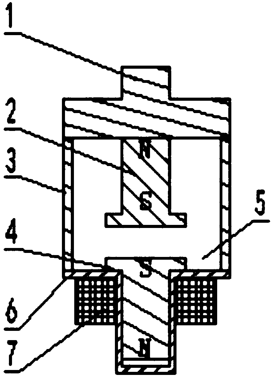
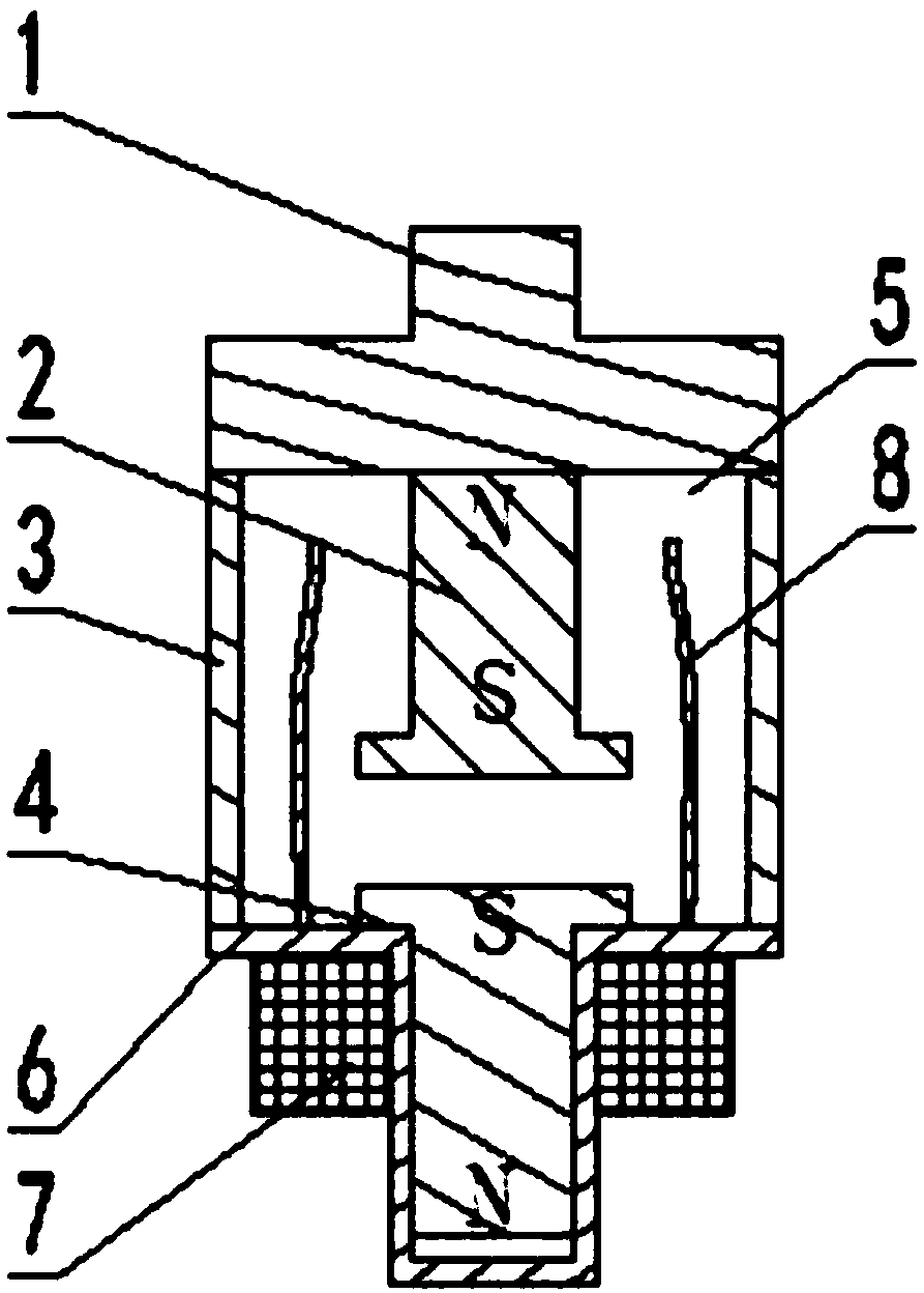
[0018] An electric permanent magnet circuit breaker, such as figure 1 , figure 2 As shown, it includes a moving contact group, a static contact group and an arc extinguishing chamber 5. The static contact group includes a static contact seat 1 and a permanent magnet static contact 2 fixedly connected to it; the moving contact The set includes a moving contact seat 6, a moving contact 4 electrically connected to the moving contact seat 6, and a moving contact wound around the moving contact for changing the magnetic pole of the moving contact 4 so as to control the opening and closing of the moving contact 4 and the permanent magnet static contact 2. The excitation coil 7 on the outer periphery of the head 4, the end of the excitation coil 7 applies pulse current; the outer periphery of the static contact seat 1 is connected to the outer periphery of the movable contact seat 6 through the sealing body 3 to form a sealed arc extinguishing chamber 5 .

[0019] The inner end of ...

Embodiment 2

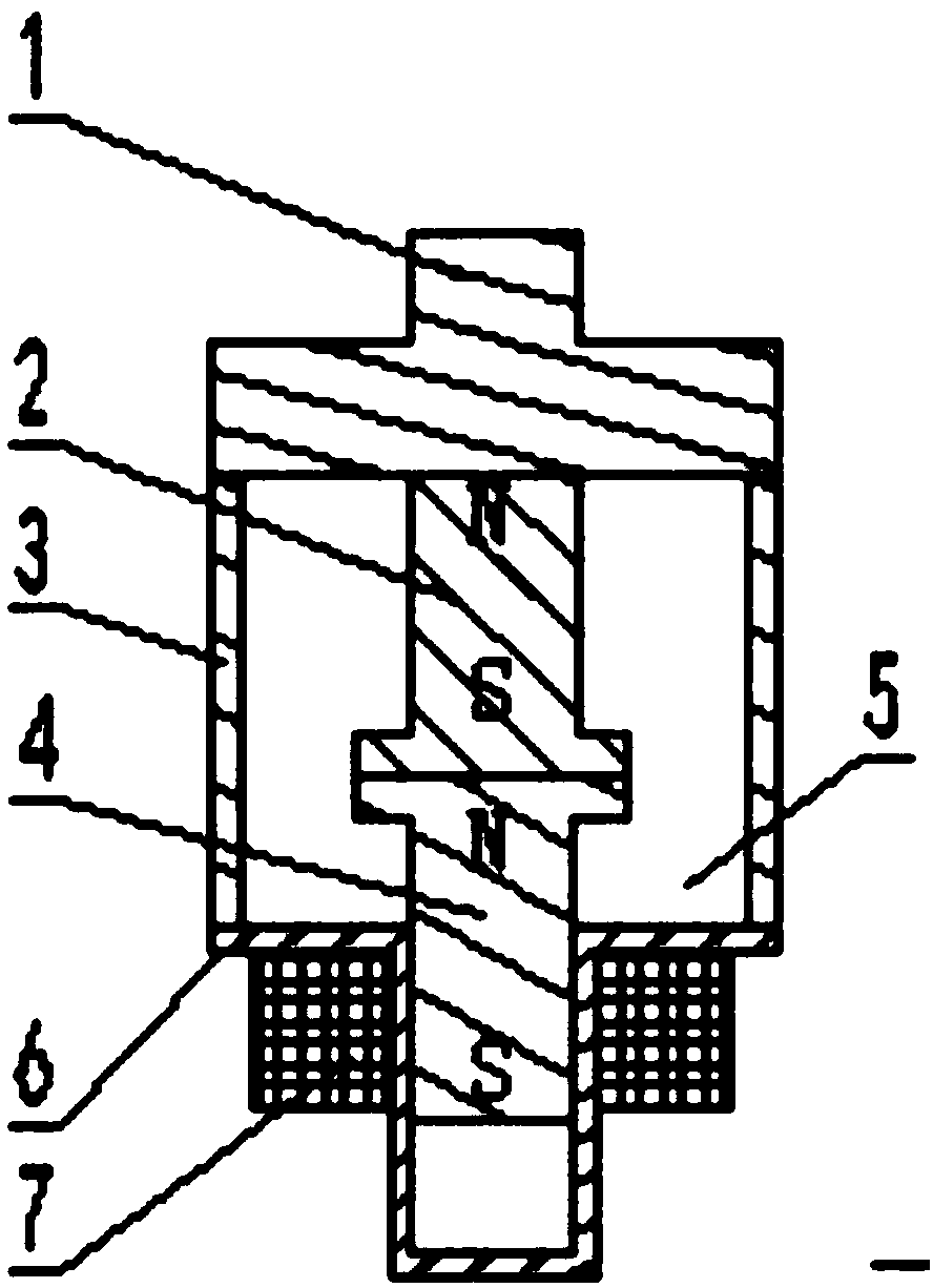
[0022] An electric permanent magnet circuit breaker, such as image 3 , Figure 4 As shown, it includes a moving contact group, a static contact group and an arc extinguishing chamber 5. The static contact group includes a static contact seat 1 and a permanent magnet static contact 2 fixedly connected to it; the moving contact The set includes a moving contact seat 6, a moving contact 4 electrically connected to the moving contact seat 6, and a moving contact wound around the moving contact for changing the magnetic pole of the moving contact 4 so as to control the opening and closing of the moving contact 4 and the permanent magnet static contact 2. The excitation coil 7 on the outer periphery of the head 4, the end of the excitation coil 7 applies pulse current; the outer periphery of the static contact seat 1 is connected to the outer periphery of the movable contact seat 6 through the sealing body 3 to form a sealed arc extinguishing chamber 5 .

[0023] On the moving con...


PUM


Abstract

The invention relates to an electric-permanent-magnet breaker. The electric-permanent-magnet breaker comprises a movable contact group, a static contact group and an arc extinction chamber and is characterized in that the static contact group comprises a static contact seat and a permanent-magnet static contact fixedly connected with the static contact seat; the movable contact group comprises a movable contact seat, a movable contact and an excitation coil, the movable contact is electrically connected with the movable contact seat, the excitation coil is used for changing the magnetic pole of the movable contact to control the contacting and separating of the movable contact and the permanent-magnet static contact and winds the periphery of the movable contact, and pulse currents are applied to the end of the excitation coil. The electric-permanent-magnet breaker has the advantages that the breaker is simple in structure, the arc extinction chamber is completely sealed and isolated,the pulse currents are applied to the excitation coil to control the contacting and separating of the movable contact and the static contact, operation reliability is achieved, control convenience andflexibility are achieved, the service life of the breaker is prolonged, and accident occurrence rate is lowered.

Description

technical field [0001] The invention relates to a circuit breaker, in particular to an electric permanent magnet circuit breaker. Background technique [0002] At present, there are many types of circuit breaker switches. Regardless of whether the arc extinguishing chamber adopts SF6 arc extinguishing, vacuum arc extinguishing or oil arc extinguishing, due to the driving of the moving contact, the arc extinguishing chamber cannot be completely sealed and isolated, resulting in failure of the seal. run accident. The patent document with the application number 201420849054.0 discloses a permanent magnet drive circuit breaker that uses a driving permanent magnet to control the opening and closing of the permanent magnet moving contact and the magnetic conducting static contact. The position of the driving permanent magnet changes to change the magnetic conducting static contact. The magnetic poles have the following problems: (1) the entire circuit breaker device is bulky and ...

Claims


Application Information

Patent Timeline
Patent Type & Authority Applications(China)
IPC IPC(8): H01H33/38H01H33/18
CPCH01H33/38H01H33/182
Inventor 刁俊起
Owner 刁俊起
Why Eureka
Try Eureka