Foot scanner

A scanner and foot technology, applied in the field of foot scanners, can solve problems such as single function of foot scanners and inability to meet different needs of customers, and achieve the effect of improving health status and improving accuracy

Pending Publication Date: 2018-08-21
FUJIAN TIEGONG INTELLIGENT ROBOT CO LTD
View PDF0 Cites 0 Cited by
  • Summary
  • Abstract
  • Description
  • Claims
  • Application Information

AI Technical Summary

Problems solved by technology

[0003] A foot scanner provided by the present invention aims to solve the problem that the function of the foot scanner is relatively single and cannot meet the different needs of customers

Method used


Image

  • Foot scanner
  • Foot scanner

Examples


Embodiment Construction

[0015] Specific embodiments of the present invention will be described below with reference to the accompanying drawings. In order to provide a comprehensive understanding of the present invention, many details are described below, but it will be apparent to those skilled in the art that the present invention can be practiced without these details.

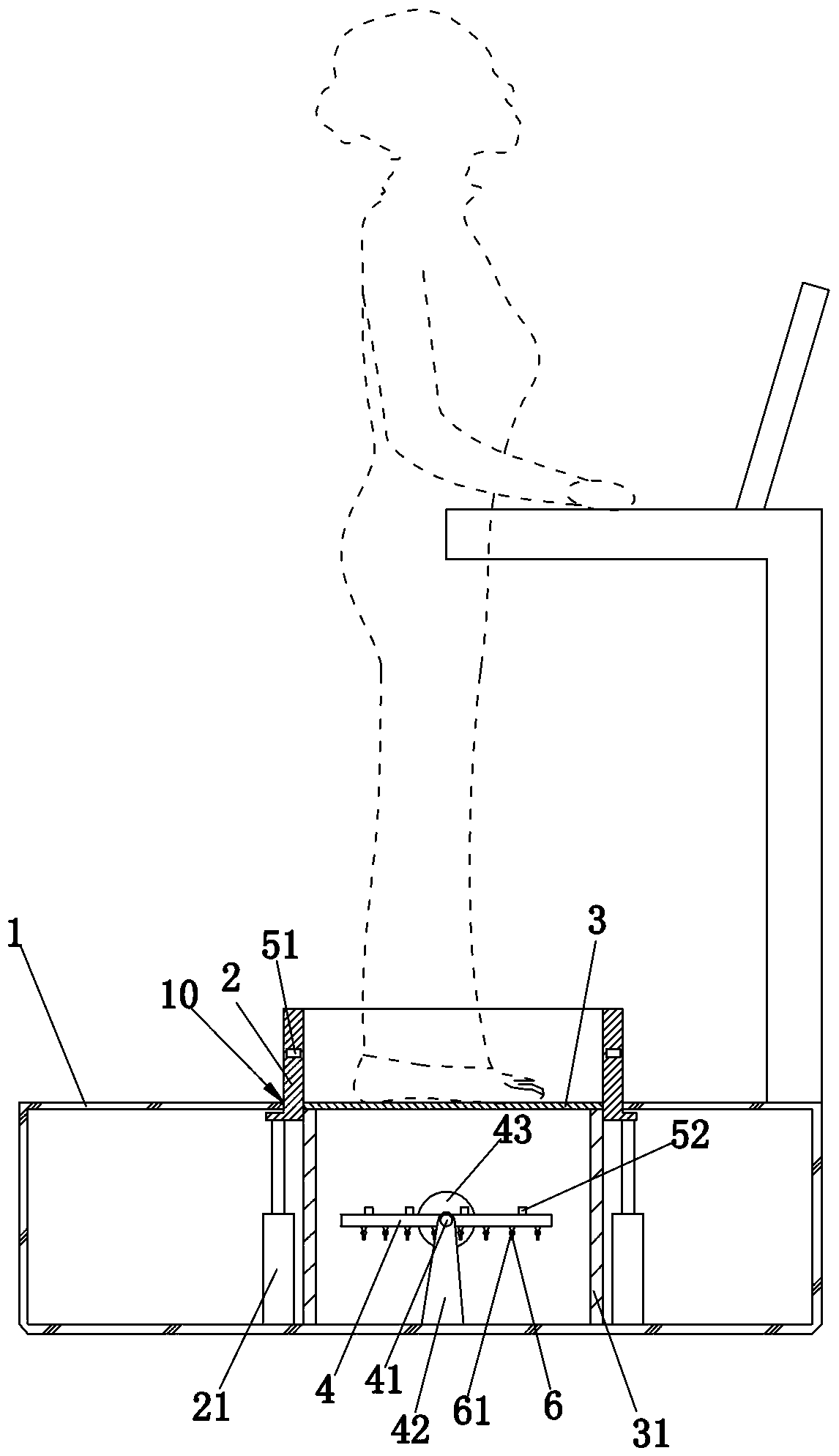
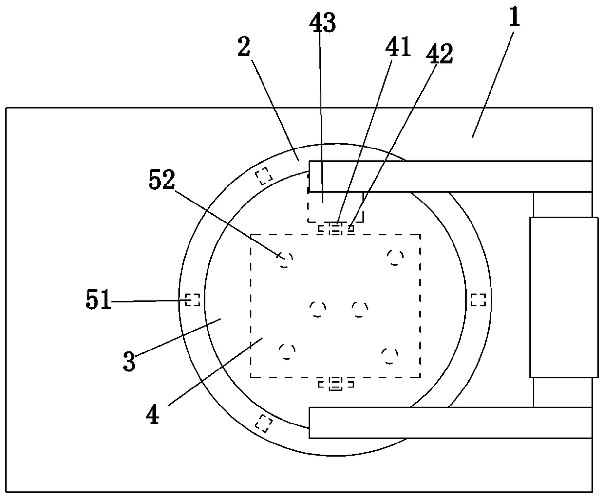
[0016] refer to figure 1 and figure 2 , a foot scanner, comprising a main body 1 , a cylinder 2 and a light-transmitting disk 3 . The upper end surface of the fuselage body 1 is provided with a hollow part 10, the lower end of the cylinder body 2 can be vertically lifted and arranged on the fuselage body 1 through a plurality of electric telescopic rods 21, and the upper end of the cylinder body 2 extends to the top of the hollow part 10, In addition, a plurality of first cameras 51 for shooting foot profile images are circularly arranged on the same horizontal plane. The inside of the main body 1 is provided with a cylindrica...


PUM


Abstract

The invention discloses a foot scanner, and relates to the field of shoe-making. The foot scanner comprises a scanner body, a cylinder body and a light-transmitting disc; a hollow portion is formed inthe scanner body; a lower end of the cylinder body is arranged on the scanner body in a vertical lifting manner, and an upper end of the cylinder body extends above the hollow portion and has a plurality of first cameras; the light-transmitting disc is fixedly arranged on the scanner body through a cylindrical supporting member, and is positioned in the cylinder body; a movably plate is vertically and rotatably arranged on the scanner body and under the light-transmitting disc; an upper end surface of the movable plate has a plurality of second cameras, and a lower end surface of the movableplate has a plurality of laser emitters which can be adjusted by swinging; and a PC upper computer, an image processing modules and a data storage module are arranged on the scanner body. The beneficial effects of the invention are that a foot 3D module is generated through the first cameras, the second cameras, and the image processing modules; suitable shoes can be selected from the data storagemodule; and the laser emitters can massage sole acupuncture points to improve the health condition of people.

Description

technical field [0001] The invention relates to the field of footwear production, and more specifically refers to a foot scanner. Background technique [0002] With the development of society, especially the rapid development of 3D scanning and 3D printing technology, the footwear industry has changed from traditional industry to modernization and automation, which has resulted in the business of customizing shoes, which uses foot scanners to acquire customers The three-dimensional information of the foot is the most important and the most basic part. Existing foot scanners have relatively single functions and cannot meet various needs of customers. Contents of the invention [0003] The purpose of the foot scanner provided by the present invention is to solve the problem that the function of the foot scanner is relatively single and cannot meet the different needs of customers. [0004] The technical scheme that the present invention adopts is as follows: [0005] A fo...

Claims


Application Information

Patent Timeline
IPC IPC(8): A43D1/02A61H39/02A61H39/00A61N5/067
CPCA43D1/025A61H39/00A61H39/02A61H2039/005A61H2205/125A61N5/067
Inventor 阙凯阙宇阙小鸿
Owner FUJIAN TIEGONG INTELLIGENT ROBOT CO LTD
Why Eureka
Try Eureka