Fan

A fan and fan blade technology, applied in the field of fans, can solve problems such as difficulty in meeting, and achieve the effect of solving resonance

Pending Publication Date: 2018-10-16
佛山勤顺科技有限公司
View PDF6 Cites 2 Cited by
  • Summary
  • Abstract
  • Description
  • Claims
  • Application Information

AI Technical Summary

Problems solved by technology

However, fans that cannot fully realize stepless speed regulation have gradually become difficult to meet the needs of the existing market and users. Therefore, it is necessary to provide a new fan structure that can realize stepless speed regulation

Method used


Image

  • Fan

Examples


Embodiment Construction

[0016] The technical solution will be described in detail below in conjunction with specific embodiments.

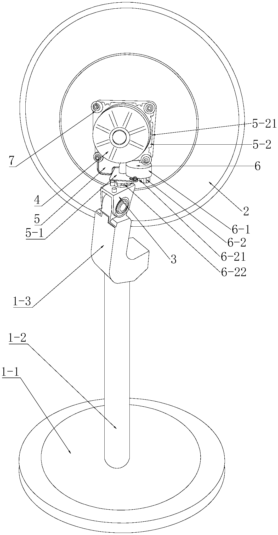
[0017] Such as figure 1 Shown, the present invention is a kind of fan, comprises fan support frame 1, front and rear grille 2, fan blade, main motor 4, motor bracket 5, shaking head device 6 and main control device, and fan blade is installed on the rotating shaft of main motor Above, the motor bracket is movably arranged on the fan support frame, and the oscillating device 6 is arranged between the motor bracket and the fan support frame. The motor bracket is provided with an elastic buffer support 7, and the motor is fixed on the elastic buffer support 7. The vibration method effectively solves the resonance problem in the process of stepless speed regulation. The elastic buffer support adopts the mode of shock-absorbing glue or spring. At least four shock-absorbing adhesives are arranged on the motor bracket, so that the motor can be stably installed on the motor br...


PUM


Abstract

The invention discloses a fan. The fan is characterized by comprising a fan support frame, front and back net covers, fan blades, a main motor, a motor bracket, a head shaking device and a main control device; the fan blades are mounted on a rotating shaft of the main motor; and the motor bracket is movably arranged on the fan support frame. The fan is characterized in that the head shaking deviceis arranged between the motor bracket and the fan support frame; an elastic buffer support is arranged on the motor bracket; and the motor is fixed on the elastic buffer support. The fan is simple instructure and convenient to use.

Description

technical field [0001] The invention relates to the technical field of fans. Background technique [0002] An electric fan is referred to as an electric fan, also known as a fan or a fan. It is a household appliance that uses a motor to drive the fan blades to rotate to accelerate the circulation of air. It is mainly used for cooling, relieving heat and circulating air. Widely used in homes, offices, shops, hospitals and hotels and other places. The floor fan is mainly composed of fan head, fan blade, net cover, pole, base and control device and other components. The pole is fixed on the base, the fan blades are installed on the fan head, and the net cover is set outside the fan blades; the fan head generally includes a motor, a motor cover, fan blades, a wind net and an oscillating air supply mechanism, and the motor drives the fan blades to run . Traditional electric fans are generally divided into several wind speed adjustments instead of stepless speed regulation. Thi...

Claims


Application Information

Patent Timeline
Patent Type & Authority Applications(China)
IPC IPC(8): F04D25/10F04D29/66
CPCF04D25/105F04D29/668
Inventor 宁勤顺
Owner 佛山勤顺科技有限公司
Why Eureka
Try Eureka