

Lifting stand column
A technology of lifting columns and screw rods, which is applied to lifting frames, lifting devices, tables with variable table heights, etc., can solve the problems of low transmission efficiency and achieve the effect of compact and simple structure
- Summary
- Abstract
- Description
- Claims
- Application Information
AI Technical Summary
Problems solved by technology
Method used
Image

Examples
Embodiment Construction
[0033] The present invention will be further described below in conjunction with the accompanying drawings and specific embodiments. It should be understood that the following "up", "down", "left", "right", "vertical", "horizontal", "inner", "outer", "vertical", "horizontal", " Words such as "top", "bottom", etc. indicating orientation or positional relationship are only based on the orientation or positional relationship shown in the drawings, and are only for the convenience of describing the present invention and simplifying the description, rather than indicating or implying that the referred device / element must have a specific orientation or are constructed and operative in a particular orientation and therefore are not to be construed as limiting the invention.
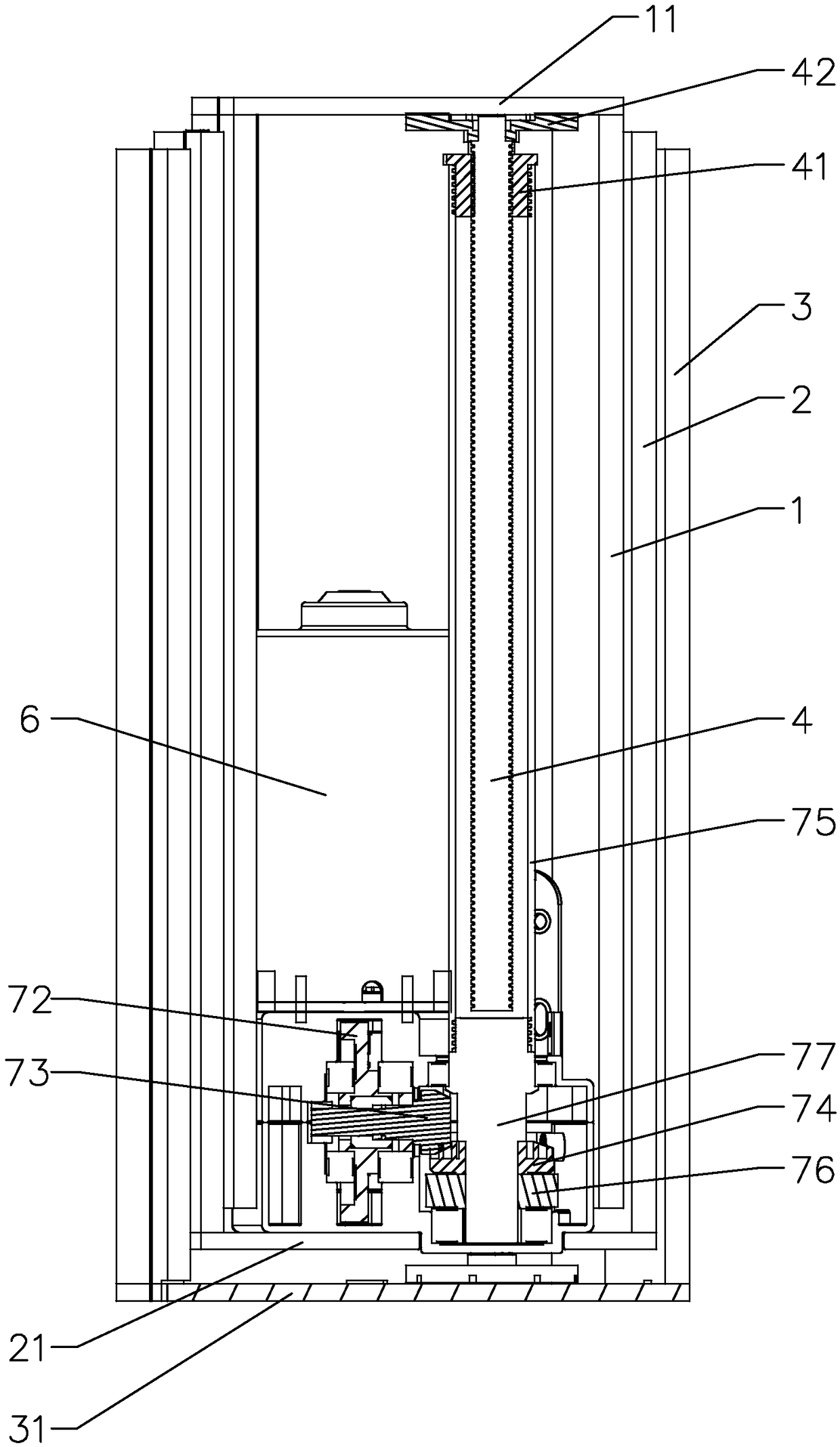
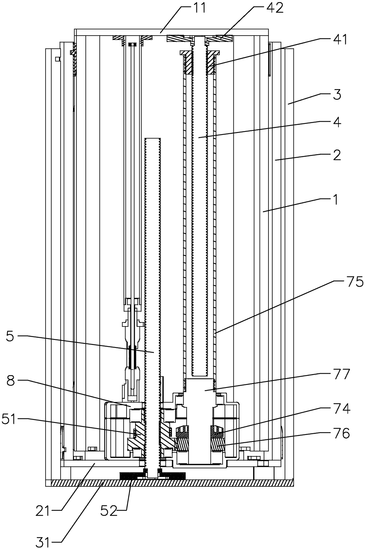
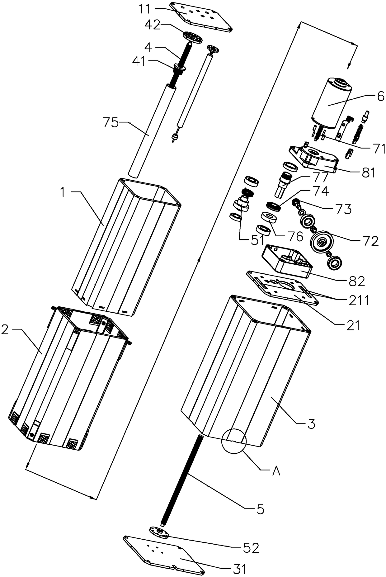
[0034] Such as Figures 1 to 5As shown, the present invention provides a lifting column, comprising an inner tube 1, a middle tube 2, an outer tube 3, a first screw mandrel 4, a second screw mandrel 5 and a dri...
PUM
 Abstract
Description
Claims
Application Information