Winding device

A winding device and winding device technology, applied in the direction of winding strips, transportation and packaging, and conveying filamentous materials, etc., can solve the problems of waste of resources, high maintenance costs, and large space occupation, so as to improve precision and Qualification rate, guaranteed quality and flatness, and the effect of saving production costs

Active Publication Date: 2018-12-11
TAICANG HONGHAI PRECISION MACHINERY CO LTD
View PDF23 Cites 4 Cited by
  • Summary
  • Abstract
  • Description
  • Claims
  • Application Information

AI Technical Summary

Problems solved by technology

[0002] At present, for electronic packaging materials, copper foil and aluminum foil, paper, silica gel, foam and other fine-density imported materials on the market, it is necessary to use a plastic baffle to control the edge coefficient and the flatness of the winding end surface. , precision, but this kind of winding mechanism is difficult to control. Generally, enterprises press the pressure wheel directly on the winding disk, such as figure 1 As shown, the winding wire is wound on the winding disk through the reciprocating movement of the pressure roller in the axial direction. When the winding wire is wound to the edge of the winding disk, the disk wall blocks the displacement of the pressure roller, so that The wire cannot move to the edge, and needs to slide to the edge through angular deflection, especially when the ultra-narrow width material is wound to the edge of the reel, due to the problem of deflection angle, the material will reach the edge of the reel and the line will be irregular and the end surface will be poor , the level is not uniform, the accuracy cannot be guaranteed, and it often cannot meet the market needs
[0003] In addition, when workers are loading materials, they need one hand to lift the pressure roller and then wind the winding on the roller, which is cumbersome and inconvenient to adjust the winding position. Some companies choose cylinders to control the pressure rollers. In this way, the air source needs to be equipped at the same time and the control system is required to control the work of the cylinder, and the cylinder support needs to be set separately, which requires high position setting, takes up a large space, high production cost, inconvenient operation, and high daily maintenance cost.
[0004] There are also many manufacturers who use floating rollers to adjust the tension, that is, through the weight of the floating rollers. Different floating rollers are required for different windings. This requires many different floating rollers for backup, which wastes resources and is inconvenient for tension adjustment.

Method used


Image

  • Winding device
  • Winding device
  • Winding device

Examples


Embodiment Construction

[0034] In order to make the object, technical solution and advantages of the present invention clearer, the present invention will be further described in detail below in conjunction with the accompanying drawings and embodiments. It should be understood that the specific embodiments described here are only used to explain the present invention, not to limit the present invention.

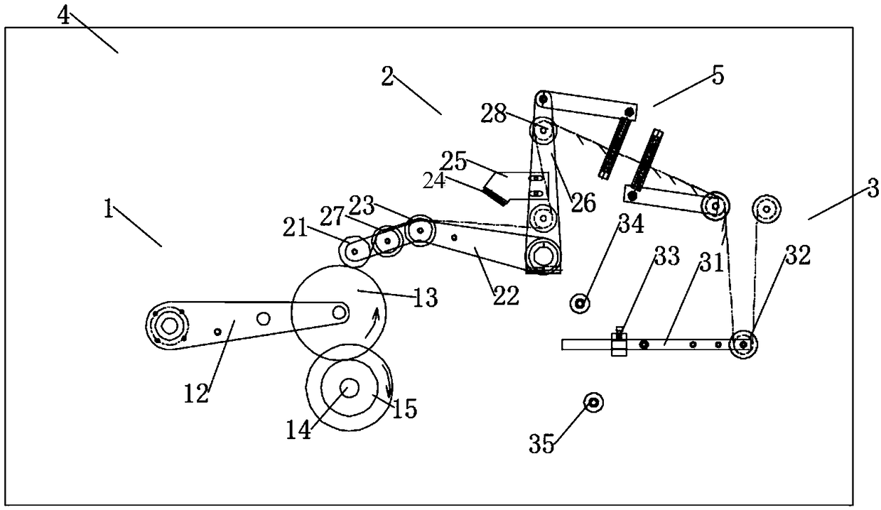
[0035] A winding device of the present invention, such as Figure 2-6 As shown, it includes a winding device 1, a pressing wheel device 2, a tension adjusting device 3, and a machine platform 4, wherein the winding device 1, pressing wheel device 2 and tension adjusting device 3 are sequentially arranged on the machine platform 4 , the winding wire passes through the tension adjustment device 3 and then through the pressure wheel device 2 and then through the winding device 1 for winding;

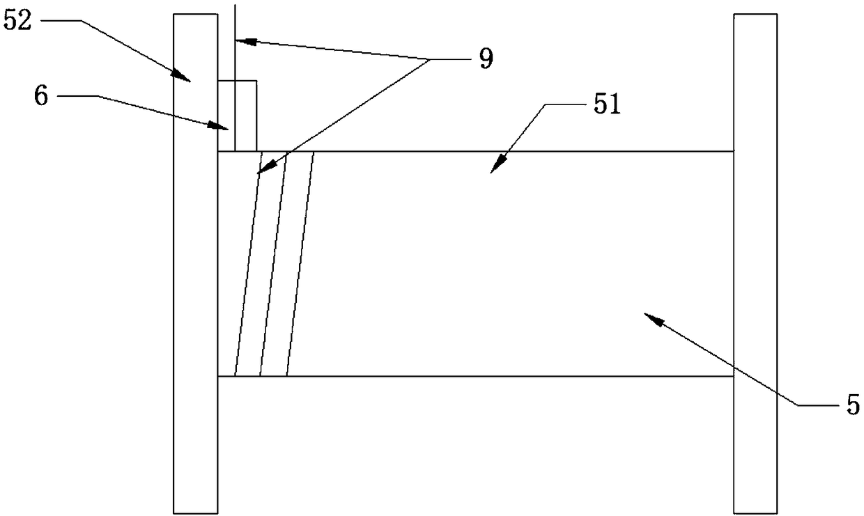
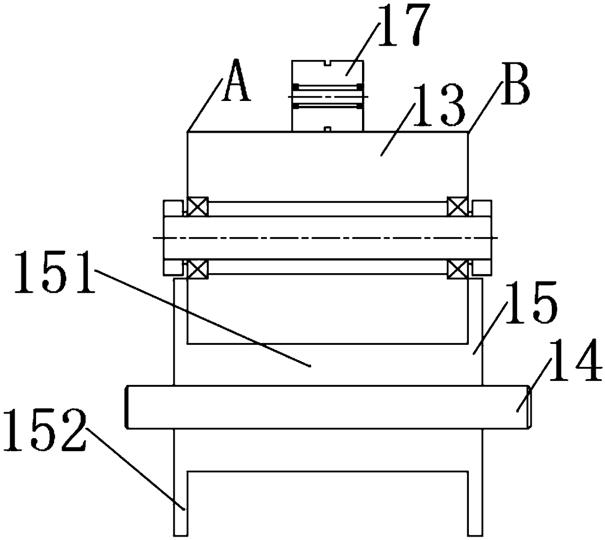
[0036] The rewinding device 1 includes a pinch arm 12, a large pinch wheel 13, a rewind shaft 14, and a reel...


PUM


Abstract

The invention discloses a winding device. The winding device includes a roll-up device, a pressing wheel device, a tension adjusting device and a machine table; the roll-up device, the pressing wheeldevice and the tension adjusting device are sequentially arranged on the machine table, andafter passing through the tension adjusting device and then passing through the pressing wheel device, a wound wire is wound through the roll-up device; a large pressing wheel is arranged between a small pressing wheel and a roll-up disc to play a role of transition, therefore, the small pressing wheel getsaway from limit of the roll-up disc, the small pressing wheel does reciprocating movement on the surface of the large pressing wheel and can move to the very edge of the large pressing wheel, meanwhile, the axial distance of the large pressing wheel is the same as that of thecore of the roll-up disc so that the wound wire can be directly guided to the edge of the roll-up disc through cooperation of the small pressing wheel and the large pressing wheel, the problem of edge wire winding is solved, the end face is flat, the wound wire has the sense of layering, the accuracy of products is greatlyimproved, and the qualification rate of the products is greatly increased.

Description

technical field [0001] The invention relates to the field of winding transmission, in particular to a winding device. Background technique [0002] At present, for electronic packaging materials, copper foil and aluminum foil, paper, silica gel, foam and other fine-density imported materials on the market, it is necessary to use a plastic baffle to control the edge coefficient and the flatness of the winding end surface. , precision, but this kind of winding mechanism is difficult to control. Generally, enterprises press the pressure wheel directly on the winding disk, such as figure 1 As shown, the winding wire is wound on the winding disk through the reciprocating movement of the pressure roller in the axial direction. When the winding wire is wound to the edge of the winding disk, the disk wall blocks the displacement of the pressure roller, so that The wire cannot move to the edge, and needs to slide to the edge through angular deflection, especially when the ultra-narr...

Claims


Application Information

Patent Timeline
Patent Type & Authority Applications(China)
IPC IPC(8): B65H54/28B65H54/70B65H59/10
CPCB65H18/10B65H18/26B65H23/16B65H23/26B65H54/28B65H54/70B65H59/10B65H2701/1944
Inventor 张建浩
Owner TAICANG HONGHAI PRECISION MACHINERY CO LTD
Why Eureka
Try Eureka