

Spike assisting equipment for sports volleyball teaching
A kind of auxiliary equipment, volleyball technology, applied in the direction of sports accessories, etc., can solve the problems of waste, different height and angle of artificial serving, and achieve the effect of convenient operation.
- Summary
- Abstract
- Description
- Claims
- Application Information
AI Technical Summary
Problems solved by technology
Method used
Image

Examples
Embodiment 1
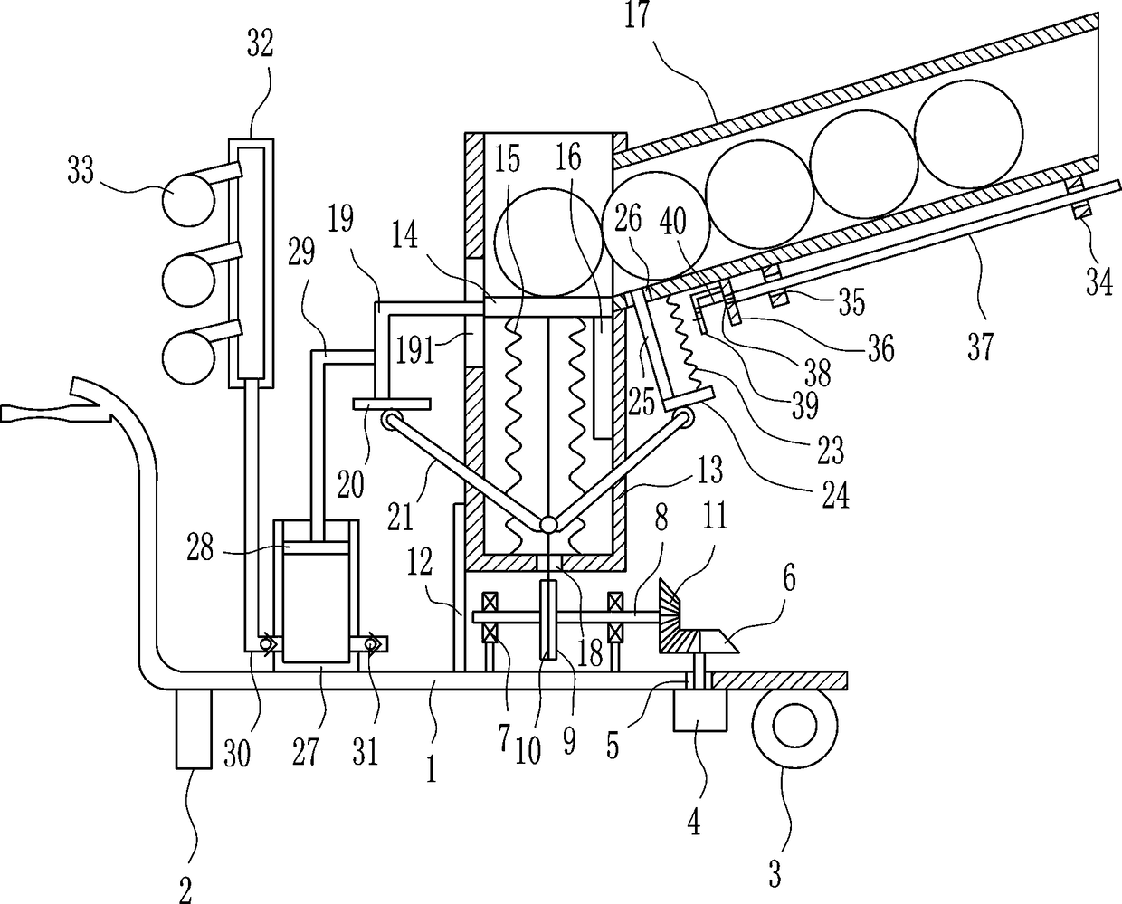
[0019] A kind of spiking auxiliary equipment for sports volleyball teaching, such as figure 1 As shown, it includes a moving plate 1, a first fixed block 2, a roller 3, a motor 4, a toothless bevel gear 6, a bearing seat 7, a rotating rod 8, a winding wheel 9, a first steel wire rope 10, and a first bevel gear 11 , mounting plate 12, placement cylinder 13, lifting plate 14, first spring 15, baffle plate 16 and ball barrel 17, the front and rear symmetrical formula on the left side of the moving plate 1 bottom is provided with the first fixed block 2, the right side of the moving plate 1 bottom The roller 3 is arranged front and back symmetrically, the motor 4 is arranged on the right side of the bottom of the moving plate 1, the motor 4 is located on the left side of the roller 3, the first through hole 5 is opened on the right part of the moving plate 1, and the output shaft of the motor 4 passes through the first through hole. The hole 5, the output shaft of the motor 4 is p...
Embodiment 2
[0021] A kind of spiking auxiliary equipment for sports volleyball teaching, such as figure 1 As shown, it includes a moving plate 1, a first fixed block 2, a roller 3, a motor 4, a toothless bevel gear 6, a bearing seat 7, a rotating rod 8, a winding wheel 9, a first steel wire rope 10, and a first bevel gear 11 , mounting plate 12, placement cylinder 13, lifting plate 14, first spring 15, baffle plate 16 and ball barrel 17, the front and rear symmetrical formula on the left side of the moving plate 1 bottom is provided with the first fixed block 2, the right side of the moving plate 1 bottom The roller 3 is arranged front and back symmetrically, the motor 4 is arranged on the right side of the bottom of the moving plate 1, the motor 4 is located on the left side of the roller 3, the first through hole 5 is opened on the right part of the moving plate 1, and the output shaft of the motor 4 passes through the first through hole. The hole 5, the output shaft of the motor 4 is p...
Embodiment 3
[0024] A kind of spiking auxiliary equipment for sports volleyball teaching, such as figure 1 As shown, it includes a moving plate 1, a first fixed block 2, a roller 3, a motor 4, a toothless bevel gear 6, a bearing seat 7, a rotating rod 8, a winding wheel 9, a first steel wire rope 10, and a first bevel gear 11 , mounting plate 12, placement cylinder 13, lifting plate 14, first spring 15, baffle plate 16 and ball barrel 17, the front and rear symmetrical formula on the left side of the moving plate 1 bottom is provided with the first fixed block 2, the right side of the moving plate 1 bottom The roller 3 is arranged front and back symmetrically, the motor 4 is arranged on the right side of the bottom of the moving plate 1, the motor 4 is located on the left side of the roller 3, the first through hole 5 is opened on the right part of the moving plate 1, and the output shaft of the motor 4 passes through the first through hole. The hole 5, the output shaft of the motor 4 is p...
PUM
 Abstract
Description
Claims
Application Information