Longitudinal beam sliding device of large displacement telescopic device for medium and low speed maglev bridge

A technology of telescopic device and sliding device, which is applied in the direction of bridges, bridge parts, bridge construction, etc., can solve the problem that the F-rail expansion joint cannot adapt to the large-displacement expansion and contraction of the track beam, and achieves the guarantee of large-scale expansion and contraction deformation and large longitudinal displacement expansion and contraction , The effect of ensuring driving safety

Pending Publication Date: 2018-12-18
CHINA RAILWAY MAGLEV TRANSPORTATION INVESTMENT CONSTR CO LTD
View PDF0 Cites 4 Cited by
  • Summary
  • Abstract
  • Description
  • Claims
  • Application Information

AI Technical Summary

Problems solved by technology

[0011] Aiming at at least one of the above defects or improvement needs in the prior art, the present invention provides a longitudinal beam sliding device for a large displacement telescopic device of a medium-low speed maglev bridge. The joint cannot adapt to the problem of large-displacement expansion and contraction of track beams, and is suitable for large-displacement expansion and contraction of large-span track beams or long-connected continuous track beams

Method used


Image

  • Longitudinal beam sliding device of large displacement telescopic device for medium and low speed maglev bridge
  • Longitudinal beam sliding device of large displacement telescopic device for medium and low speed maglev bridge
  • Longitudinal beam sliding device of large displacement telescopic device for medium and low speed maglev bridge

Examples


Embodiment Construction

[0066] In order to make the object, technical solution and advantages of the present invention clearer, the present invention will be further described in detail below in conjunction with the accompanying drawings and embodiments. It should be understood that the specific embodiments described here are only used to explain the present invention, not to limit the present invention. In addition, the technical features involved in the various embodiments of the present invention described below can be combined with each other as long as they do not constitute a conflict with each other. The present invention will be further described in detail below in combination with specific embodiments.

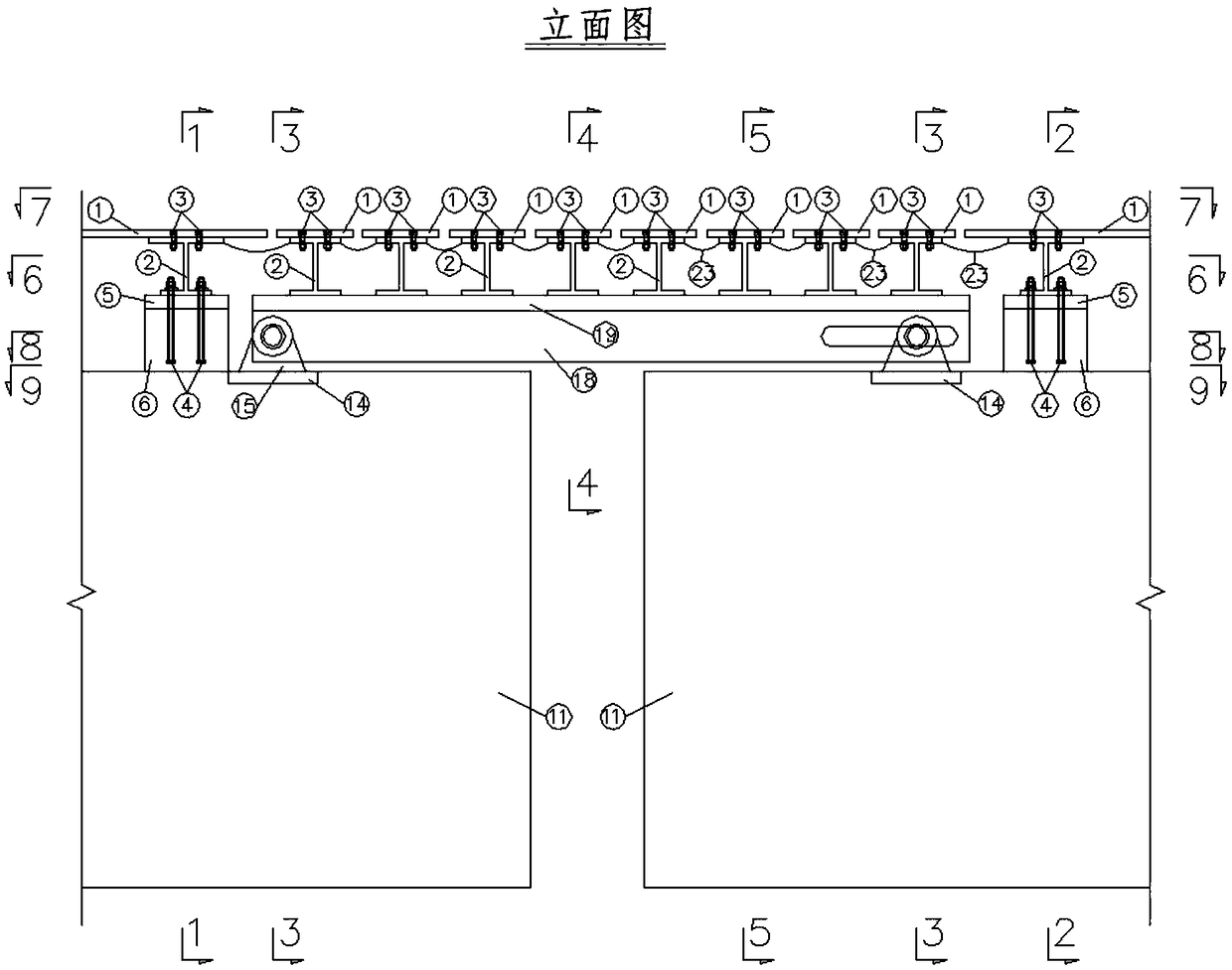
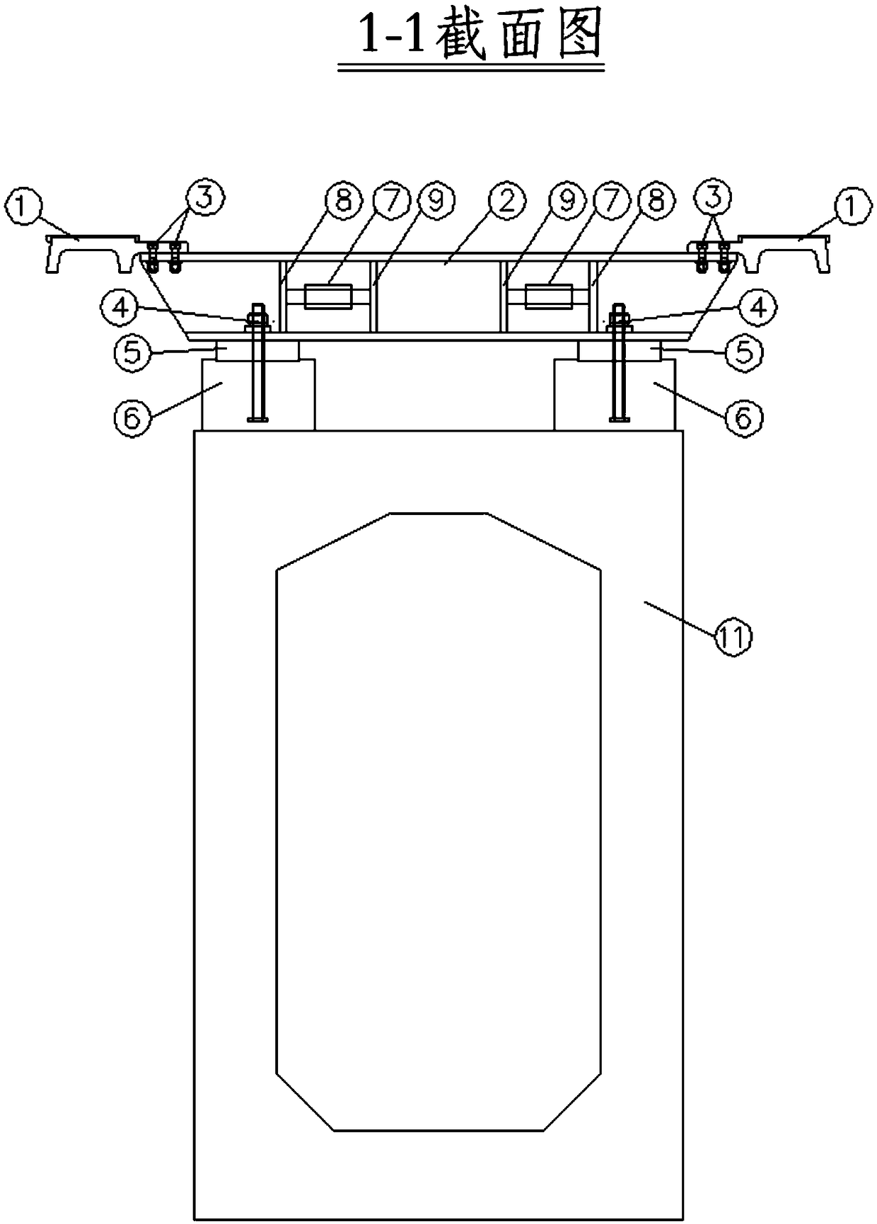
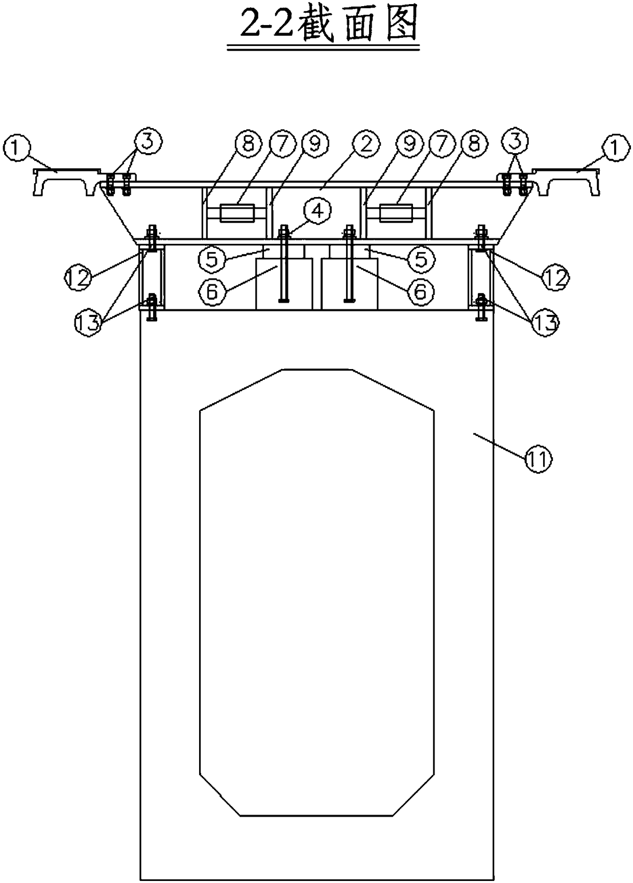
[0067] Such as Figure 1-19 As shown, the longitudinal girder sliding device of the medium-low speed maglev bridge large-displacement telescopic device of the present invention, the large-displacement telescopic device spans and is arranged on the beam gap of the medium-low speed maglev rai...


PUM


Abstract

The invention discloses a longitudinal beam sliding device of a large displacement expansion device of a medium-low speed maglev bridge, wherein, a terminal rail row structure and a support of the expansion device are respectively arranged on the beam tops of two beam ends of adjacent rail beams;, a simple supporting small longitudinal beam is arranged Between that support of the telescopic device, and the upper end of the simple supporting small longitudinal beam is slidably provided with a modular telescopic rail row through the sliding device of the longitudinal beam; A cushion structure made of wear-resisting material is arranged between the longitudinal beam sliding device and the modular telescopic rail row; The modular telescopic rail row comprises a plurality of rail row sub-units;The rail beam of the rail row sub-unit and the rail row structure of the terminal end are provided with a lateral moving device; A link device is arranged between two adjacent rail row sub-units andbetween that rail row structure and the end of the rail row, and the two end of the link device are connected with a lateral moving device. The invention solves the problem that the I-type, II-type and III-type F rail expansion joints cannot adapt to the large displacement expansion and contraction of the track beam, and is suitable for the large displacement expansion and contraction of the long-span track beam or the long-link continuous track beam.

Description

technical field [0001] The invention belongs to the field of medium-low speed maglev rail transit, and in particular relates to a longitudinal beam sliding device of a large-displacement expansion and contraction device for a medium-low speed maglev bridge. Background technique [0002] The medium and low-speed maglev rail transit adopts the suspension and guidance technology of the constant electromagnet suction type, and realizes the suspension and guidance of the vehicle through the electromagnetic attraction between the U-shaped electromagnet on the vehicle suspension frame and the F-shaped rail. At present, the middle and low speed maglev track beam structure and track structure are divided into two parts. The track structure is laid on the top of the concrete track beam. , The expansion and contraction of the track structure. [0003] At present, there are conventional slotted track joints for medium and low-speed maglev transportation (including type I, type II, and ...

Claims


Application Information

Patent Timeline
Patent Type & Authority Applications(China)
IPC IPC(8): E01B25/30E01D19/06
CPCE01B25/305E01D19/06
Inventor 龚俊虎谢海林鄢巨平张家炳
Owner CHINA RAILWAY MAGLEV TRANSPORTATION INVESTMENT CONSTR CO LTD
Why Eureka
Try Eureka