Worn medical adhesive tape pull-parting device

A wearable and tape technology, applied in the field of wearable medical tape tearing devices, can solve the problems of troublesome operation, falling needles, reducing tape viscosity, etc., and achieves the effects of good tearing, avoiding tape displacement and simple operation.

Active Publication Date: 2018-12-21
THE AFFILIATED HOSPITAL OF QINGDAO UNIV
View PDF8 Cites 2 Cited by
  • Summary
  • Abstract
  • Description
  • Claims
  • Application Information

AI Technical Summary

Problems solved by technology

[0002] During the infusion, in order to prevent the infusion tube and the needle from moving and causing the needle to fall off the patient's hand, it is necessary to stick the infusion tube and the needle to the

Method used


Image

  • Worn medical adhesive tape pull-parting device
  • Worn medical adhesive tape pull-parting device
  • Worn medical adhesive tape pull-parting device

Examples


Example Embodiment

[0017] Example 1

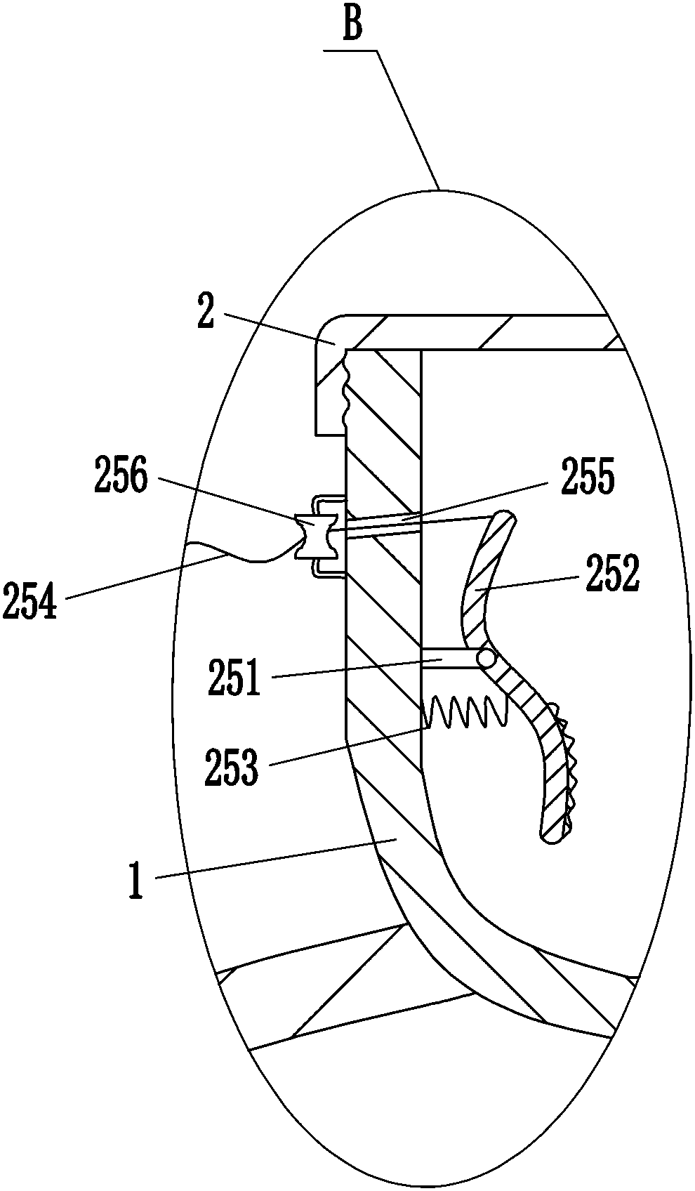
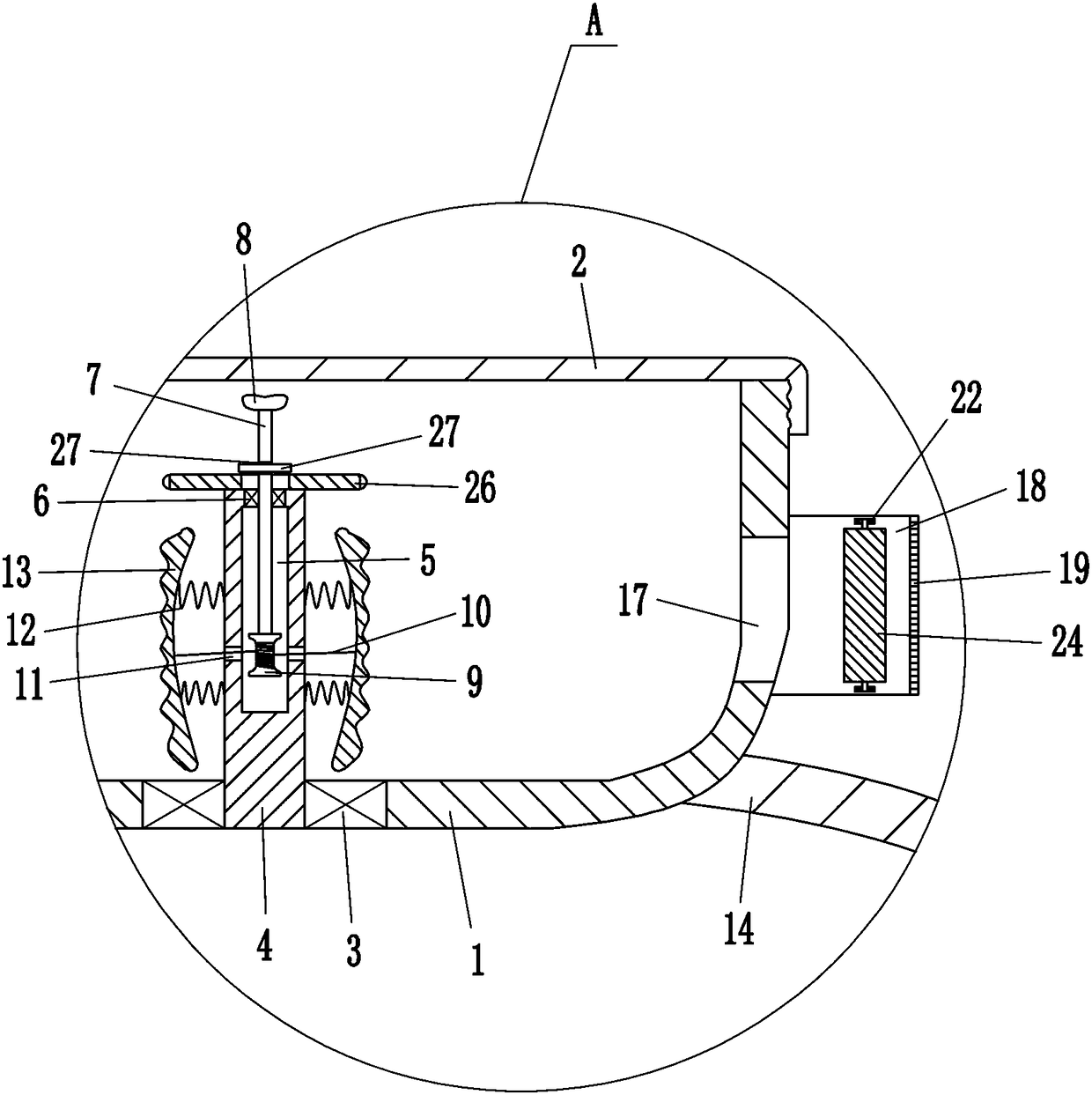
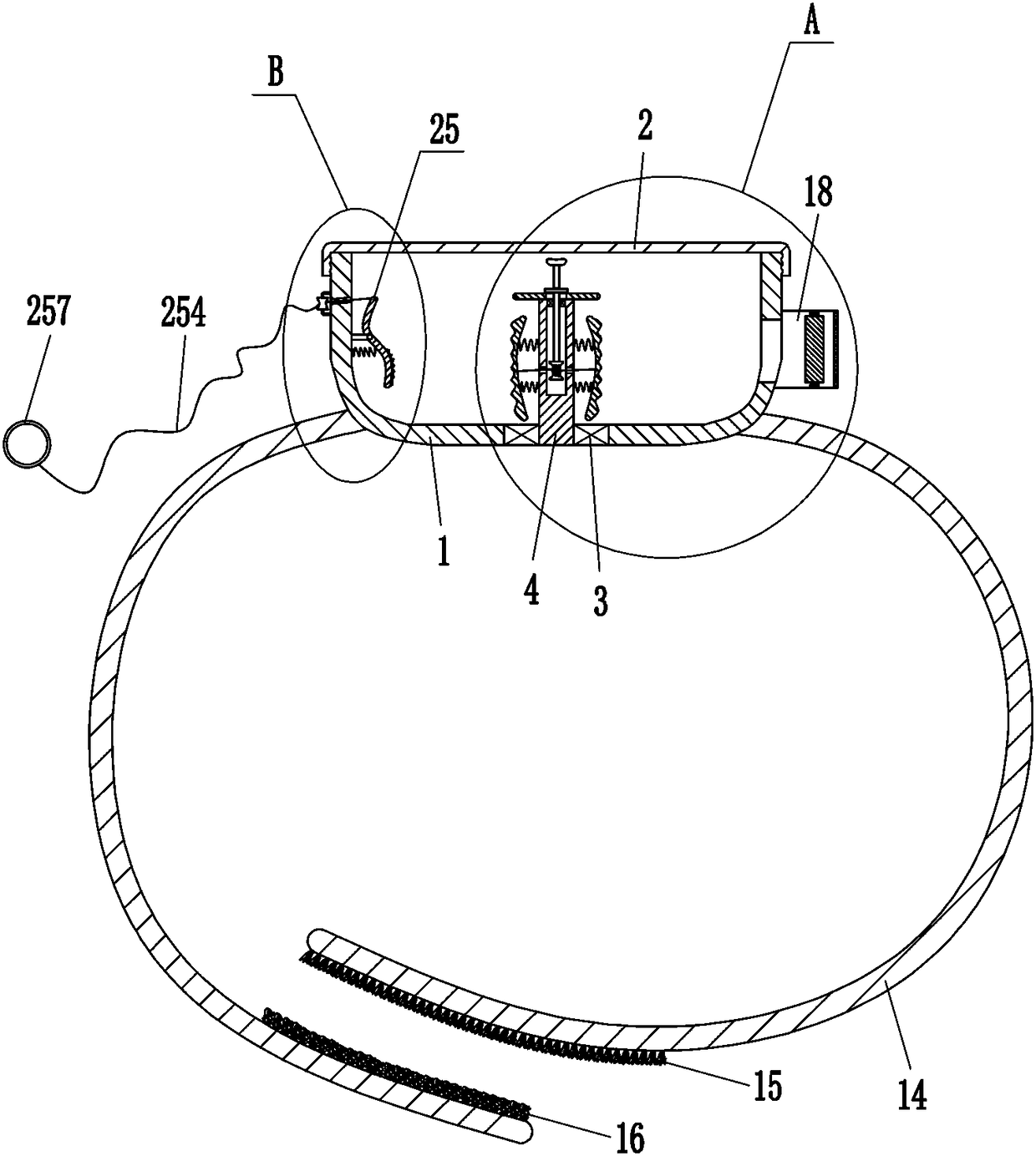
[0018] A wearable medical tape tearing device, such as Figure 1-4 As shown, it includes a cylindrical box body 1, a cover 2, a first bearing seat 3, a rotating shaft 4, a second bearing seat 6, a rotating rod 7, a knob 8, a bobbin 9, a pull wire 10, a first spring 12, a pressure Block 13, lace 14, Velcro male buckle 15, Velcro female buckle 16, mounting plate 18, toothed blade 19, sleeve 20, sleeve 21, third bearing seat 22, second spring 23 and roller 24, The top of the cylindrical box body 1 is provided with a cover 2, and the cover 2 is matched with the cylindrical box body 1. A first bearing seat 3 is embedded in the middle of the bottom of the cylindrical box body 1, and a rotating shaft 4 is connected in the first bearing seat 3. A cavity 5 is opened on the rotating shaft 4, a second bearing seat 6 is embedded in the top of the rotating shaft 4, a rotating rod 7 is connected in the second bearing seat 6, a knob 8 is connected to the top of the rotating ...

Example Embodiment

[0019] Example 2

[0020] A wearable medical tape tearing device, such as Figure 1-4 As shown, it includes a cylindrical box body 1, a cover 2, a first bearing seat 3, a rotating shaft 4, a second bearing seat 6, a rotating rod 7, a knob 8, a bobbin 9, a pull wire 10, a first spring 12, a pressure Block 13, lace 14, Velcro male buckle 15, Velcro female buckle 16, mounting plate 18, toothed blade 19, sleeve 20, sleeve 21, third bearing seat 22, second spring 23 and roller 24, The top of the cylindrical box body 1 is provided with a cover 2, and the cover 2 is matched with the cylindrical box body 1. A first bearing seat 3 is embedded in the middle of the bottom of the cylindrical box body 1, and a rotating shaft 4 is connected in the first bearing seat 3. A cavity 5 is opened on the rotating shaft 4, a second bearing seat 6 is embedded in the top of the rotating shaft 4, a rotating rod 7 is connected in the second bearing seat 6, a knob 8 is connected to the top of the rotating ...

Example Embodiment

[0022] Example 3

[0023] A wearable medical tape tearing device, such as Figure 1-4 As shown, it includes a cylindrical box body 1, a cover 2, a first bearing seat 3, a rotating shaft 4, a second bearing seat 6, a rotating rod 7, a knob 8, a bobbin 9, a pull wire 10, a first spring 12, a pressure Block 13, lace 14, Velcro male buckle 15, Velcro female buckle 16, mounting plate 18, toothed blade 19, sleeve 20, sleeve 21, third bearing seat 22, second spring 23 and roller 24, The top of the cylindrical box body 1 is provided with a cover 2, and the cover 2 is matched with the cylindrical box body 1. A first bearing seat 3 is embedded in the middle of the bottom of the cylindrical box body 1, and a rotating shaft 4 is connected in the first bearing seat 3. A cavity 5 is opened on the rotating shaft 4, a second bearing seat 6 is embedded in the top of the rotating shaft 4, a rotating rod 7 is connected in the second bearing seat 6, a knob 8 is connected to the top of the rotating ...


PUM


Abstract

The invention relates to a pull-parting device, in particular to a worn medical adhesive tape pull-parting device. For solving the technical problem, the worn medical adhesive tape pull-parting devicesimple in operation and making the stickiness of an adhesive tape not prone to reduction. According to the technical scheme, the worn medical adhesive tape pull-parting device comprises a columnar box body, a cover, a first bearing seat, a rotary shaft, a second bearing seat, a rotary rod and the like. The top of the columnar box body is provided with the cover, the cover is matched with the columnar box body, the middle of the bottom of the columnar box body is provided with the first bearing seat in an embedded way, and the rotary shat is connected in the first bearing seat and is providedwith a cavity. Under the effect of the first bearing seat, the rotary shaft can rotate with an adhesive tape so that a medical worker can better pull out the adhesive tape and pull the adhesive tape apart through a toothed blade, the operation is simple, and the stickiness of the adhesive tape is not reduced; the adhesive tape can be compressed through a compressing mechanism, the phenomenon is avoided that the adhesive tape rotates when the toothed blade pulls the adhesive tape apart, and accordingly the tooth blade can better pull the adhesive tape apart.

Description

technical field [0001] The invention relates to a tearing device, in particular to a wearable medical adhesive tape tearing device. Background technique [0002] During the infusion, in order to prevent the infusion tube and the needle from moving and causing the needle to fall off the patient's hand, it is necessary to stick the infusion tube and the needle to the patient's hand with adhesive tape. The tape sticks to one's own hands, and after enough tape is torn off, the infusion tube and needle are stuck to the patient's hand with the torn tape. Reduce the stickiness of the tape. Contents of the invention [0003] In order to overcome the disadvantages of needing medical staff to tear off the tape manually, which is cumbersome and may reduce the stickiness of the tape, the technical problem is to provide a wearable medical tape tearing device that is easy to operate and not easy to reduce the stickiness of the tape. [0004] The technical solution is: a wearable medic...

Claims


Application Information

Patent Timeline
IPC IPC(8): A61F15/02
CPCA61F15/001A61F15/02
Inventor 刘永福
Owner THE AFFILIATED HOSPITAL OF QINGDAO UNIV
Why Eureka
Try Eureka