Shower head water-saving switching structure and shower head

A shower and water seat technology, applied in the field of sanitary ware, can solve the problems of complex structure, high learning cost, waste of water resources and other problems of button switching shower, and achieve the effect of simple structure, simple operation and labor-saving operation

Pending Publication Date: 2019-01-11
PURITY XIAMEN SANITARY WARE
View PDF0 Cites 7 Cited by
  • Summary
  • Abstract
  • Description
  • Claims
  • Application Information

AI Technical Summary

Problems solved by technology

[0004] Since people do not need the large flow of water from the shower when applying shower gel and shampoo in the process of showering, at this time, the shower is in the mode of constant large flow of water, so there will be a problem of waste of water resources. For the button switch flower Sprinkler, if the water outlet flow of the shower is controlled by controlling the connection area between the water diversion port of the switch plate and the water inlet of the shower function water chamber, the water flow of the shower head is switched along the rotation axis of the switch plate and acts on the switch due to the button. On the switch plate, when the connection area between the water diversion port of the switch plate and the water inlet of the shower function water chamber is small, the force of the incoming water flow on the switch plate is the largest, resulting in a large frictional resistance when the switch plate rotates. It is very laborious to press the button with great force to drive the switching disc to rotate. Therefore, the existing push-button switch shower generally controls the water flow of the shower by adding an additional flow control component, which makes the structure of the push-button switch shower more complicated. , and the user needs to use two buttons to control the water flow of the shower and the water outlet method of the shower respectively, and the learning cost for the user is relatively high

Method used


Image

  • Shower head water-saving switching structure and shower head
  • Shower head water-saving switching structure and shower head
  • Shower head water-saving switching structure and shower head

Examples


Embodiment Construction

[0039] In order to further explain the technical solution of the present invention, the present invention will be described in detail below through specific examples.

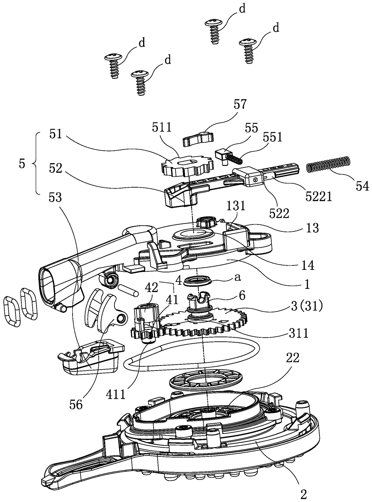
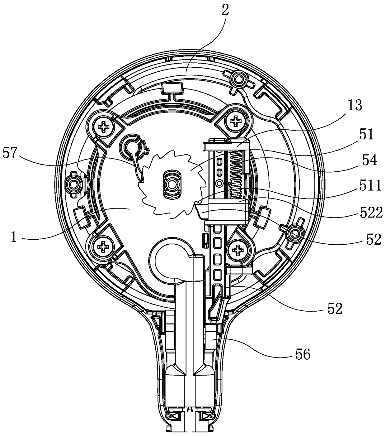
[0040] Such as Figure 1 to Figure 8 As shown, the present invention discloses a shower water-saving switching structure, which includes a water inlet seat 1 with a water inlet channel 11, a water outlet body 2 with multiple functional water chambers 21, a functional water switching member 3, and a flow switching member 4 and drive mechanism 5.

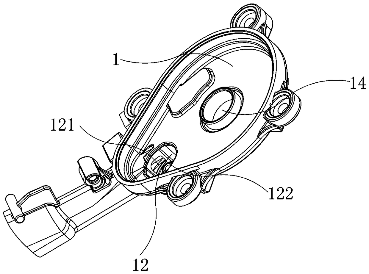
[0041] Cooperate Figure 1 to Figure 5 As shown, the water inlet seat 1 and the water outlet body 2 are connected by screws d, and a water distribution chamber A is formed between the water inlet seat 1 and the water outlet body 2; There is a sinker 12, which can be located on the water inlet seat 1, the side wall of the sinker 12 is provided with a side water inlet 121 communicating with the water inlet channel 11; the inner bottom wall of the water distribution cha...


PUM


Abstract

The invention discloses a shower head water-saving switching structure and a shower head. The shower head water-saving switching structure comprises a water inlet seat, a water outlet body, a functional water switching part, a flow switching part and a driving mechanism; the water inlet seat is connected with the water outlet body to form a water distribution cavity, and the driving mechanism comprises a ratchet wheel, a push rod linked with the ratchet wheel and a button linked with the push rod; and the functional water switching part and the flow switching part are arranged in the water distribution cavity in a rotatable mode and are linked with the ratchet wheel. The shower head water-saving switching structure and the shower head are simple in structure and labor-saving in operation.

Description

technical field [0001] The invention relates to the field of sanitary ware, in particular to a shower water-saving switching structure and a shower. Background technique [0002] With the improvement of people's living standards, people's requirements for showers are getting higher and higher, so most people will choose showers with multiple functional water options, and people control the water outlet mode of showers by switching operations. [0003] In order to make it easier for people to operate the water outlet mode of the shower, there is currently a button switch shower head that uses a single button to switch the water outlet mode. This push-button switching shower is to drive the switch plate located in the shower water distribution chamber to rotate through the button to control whether the water distribution port of the switch plate is connected to the water inlet of each functional water chamber of the shower, so as to realize functional water switching. [0004...

Claims


Application Information

Patent Timeline
Patent Type & Authority Applications(China)
IPC IPC(8): B05B1/18B05B1/30
CPCB05B1/18B05B1/30
Inventor 胡东明叶瑞寅凌兴传吴国忠
Owner PURITY XIAMEN SANITARY WARE
Why Eureka
Try Eureka