An electrical professional integrated circuit design display device

A technology of integrated circuit and display equipment, which is applied in the field of electrical professional integrated circuit design and display equipment, and can solve the problems of easy soreness, inconvenience, and easy sticking of arms

Active Publication Date: 2020-09-04
叶松霞
View PDF10 Cites 0 Cited by
  • Summary
  • Abstract
  • Description
  • Claims
  • Application Information

AI Technical Summary

Problems solved by technology

[0002] In order to increase students' knowledge of integrated circuits, various courses will be set up to teach students, among which there is an integrated circuit design demonstration course. When teaching integrated circuit design, the teacher usually holds the integrated circuit design with both hands. In order to make the students behind clearly see the integrated circuit design, it is necessary for the teacher to hold the integrated circuit design with his hands so that the arm is easy to be sore, and because the teacher's hands are occupied, it is so inconvenient for the teacher to point out the difference between the two integrated circuit designs. Point, when the weather is too hot in summer, the teacher's palms will sweat, so the sweat is easy to stick to the integrated circuit design, making the integrated circuit design dirty

Method used


Image

  • An electrical professional integrated circuit design display device
  • An electrical professional integrated circuit design display device
  • An electrical professional integrated circuit design display device

Examples


Embodiment 1

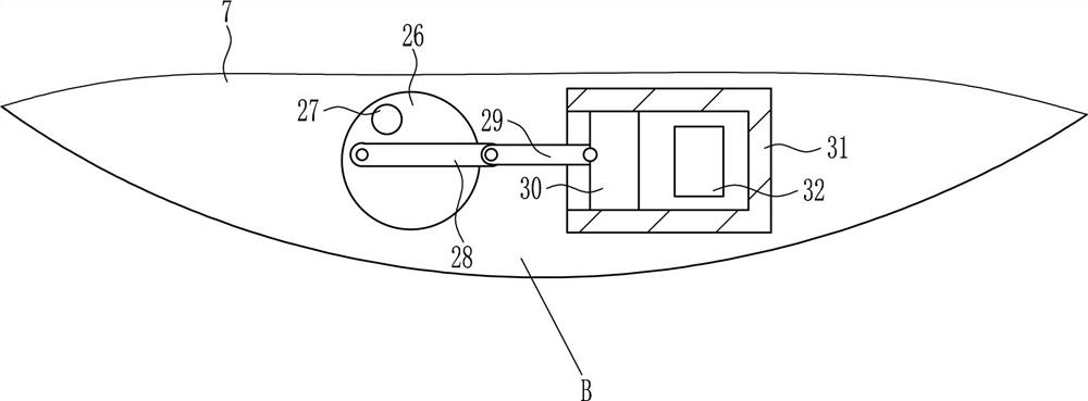
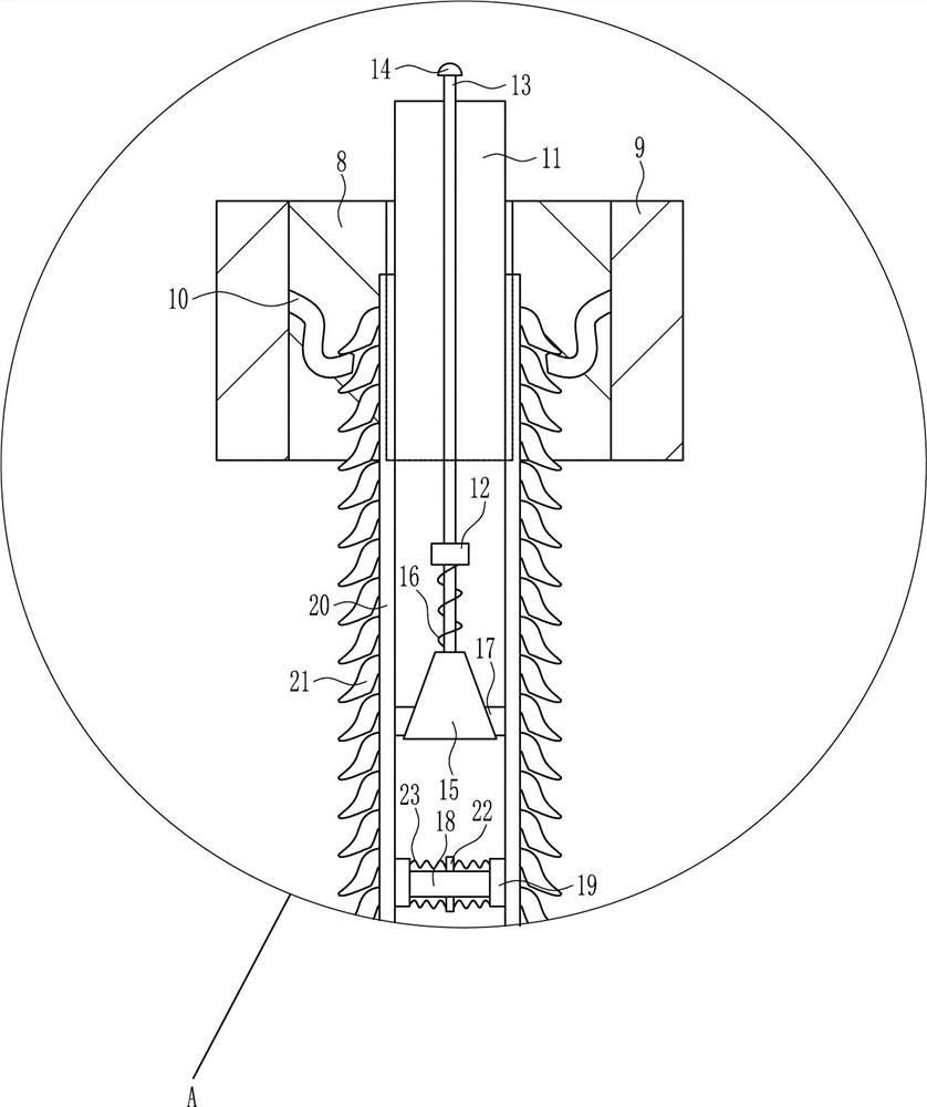
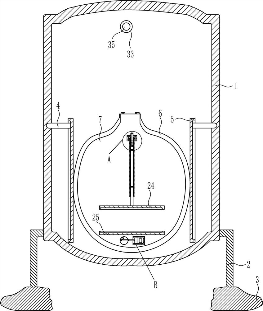
[0018] A display device for electrical professional integrated circuit design, such as Figure 1-4 As shown, it includes a placing frame 1, a leg 2, a support 3, an L-shaped rod 4, a circular plate 5, a first placing plate 6, a second placing plate 7, a slot plate 8, a connecting plate 9, and a block 10 , sliding plate 11, sliding sleeve 12, sliding rod 13, pressing block 14, equilateral trapezoidal block 15, first spring 16, wedge block 17, sliding rail 18, sliding block 19, vertical plate 20, locking teeth 21, connecting block 22. The second spring 23, the first placement groove 24 and the second placement groove 25, the lower parts of the left and right sides of the placement frame 1 are connected with outriggers 2, the bottom of the legs 2 is connected with a support 3, and the front side of the placement frame 1 L-shaped rods 4 are connected to the left and right sides of the L-shaped rod 4, and a return-shaped plate 5 is slidably arranged on the L-shaped bar 4. A first p...

Embodiment 2

[0020] A display device for electrical professional integrated circuit design, such as Figure 1-4As shown, it includes a placing frame 1, a leg 2, a support 3, an L-shaped rod 4, a circular plate 5, a first placing plate 6, a second placing plate 7, a slot plate 8, a connecting plate 9, and a block 10 , sliding plate 11, sliding sleeve 12, sliding rod 13, pressing block 14, equilateral trapezoidal block 15, first spring 16, wedge block 17, sliding rail 18, sliding block 19, vertical plate 20, locking teeth 21, connecting block 22. The second spring 23, the first placement groove 24 and the second placement groove 25, the lower parts of the left and right sides of the placement frame 1 are connected with outriggers 2, the bottom of the legs 2 is connected with a support 3, and the front side of the placement frame 1 L-shaped rods 4 are connected to the left and right sides of the L-shaped rod 4, and a return-shaped plate 5 is slidably arranged on the L-shaped bar 4. A first pl...

Embodiment 3

[0023] A display device for electrical professional integrated circuit design, such as Figure 1-4 As shown, it includes a placing frame 1, a leg 2, a support 3, an L-shaped rod 4, a circular plate 5, a first placing plate 6, a second placing plate 7, a slot plate 8, a connecting plate 9, and a block 10 , sliding plate 11, sliding sleeve 12, sliding rod 13, pressing block 14, equilateral trapezoidal block 15, first spring 16, wedge block 17, sliding rail 18, sliding block 19, vertical plate 20, locking teeth 21, connecting block 22. The second spring 23, the first placement groove 24 and the second placement groove 25, the lower parts of the left and right sides of the placement frame 1 are connected with outriggers 2, the bottom of the legs 2 is connected with a support 3, and the front side of the placement frame 1 L-shaped rods 4 are connected to the left and right sides of the L-shaped rod 4, and a return-shaped plate 5 is slidably arranged on the L-shaped bar 4. A first p...


PUM


Abstract

The invention relates to an electric professional display device, in particular to an electric professional integrated circuit design display device. The technical problem is to provide an electric professional integrated circuit design display device capable of fixedly displaying integrated circuit design and keeping integrated circuit design clean. The technical scheme of the invention is as follows: an electric professional integrated circuit design display device comprises a placing frame, a leg, a support, an L-shaped rod, a return plate, a first placing plate, a second placing plate, a slot plate, a connecting plate, a card block, a sliding plate, a sliding sleeve and the like; The lower part of the left and right sides of the placing frame is connected with legs, the bottom of the legs is connected with supports, and the left and right sides of the front side of the placing frame are connected with L-shaped bars. The first placement groove of the invention can be moved downwardand matched with the second placement groove to fix the integrated circuit design, so that the teacher can conveniently teach the students, and the teacher does not need to hold the integrated circuitdesign high to display the students.

Description

technical field [0001] The invention relates to an electrical professional display device, in particular to an electrical professional integrated circuit design display device. Background technique [0002] In order to increase students' knowledge of integrated circuits, various courses will be set up to teach students, among which there is an integrated circuit design demonstration course. When teaching integrated circuit design, the teacher usually holds the integrated circuit design with both hands. In order to make the students behind clearly see the integrated circuit design, it is necessary for the teacher to hold the integrated circuit design with his hands so that the arm is easy to be sore, and because the teacher's hands are occupied, it is so inconvenient for the teacher to point out the difference between the two integrated circuit designs. Point, when the weather is too hot in summer, the teacher's palms will sweat, so the sweat is easy to stick to the integrate...

Claims


Application Information

Patent Timeline
Patent Type & Authority Patents(China)
IPC IPC(8): G09B19/00G09B23/18
CPCG09B19/00G09B23/183
Inventor 王令剑
Owner 叶松霞
Why Eureka
Try Eureka