Lighting device used for stadium

A technology for lighting devices and sports venues, which is applied to lighting devices, fixed lighting devices, components of lighting devices, etc. It can solve the problems of large glare threshold, energy waste, poor comfort, etc., and achieve the effect of preventing glare

Inactive Publication Date: 2019-02-19
FUJIAN HONGBO OPTO ELECTRONICS TECH CO LTD
View PDF6 Cites 4 Cited by
  • Summary
  • Abstract
  • Description
  • Claims
  • Application Information

AI Technical Summary

Problems solved by technology

Among them, the matrix arrangement of the roof will cause the athletes to appear dazzling, ghosting and dizziness due to seeing the roof lights for a long time, which seriously affects the normal performance and judgment of athletes and referees
[0004] In the construction and layout of sports venues or venues, except for a few single competition purposes, most of the functions are fitness and training, and multiple venues are arranged in a centralized manner. In this case, the lighting of a unified horse track will cause a single venue to be unable to be independent. control, resulting in energy waste
[0005] Patent No. CN207778131U "A LED Lighting Fixture with Adjustable Illumination Angle" describes a lighting fixture that can adjust the irradiation angle through the louver filter. This technical solution will reduce the light loss while changing the irradiation angle. Following the change is not conducive to energy saving; in addition, if the lighting device in the above patent publication is arranged on the left and right sides of the long side of the sports field, the louver filter will be in a horizontal state with the long side of the field, and the astigmatism and overflow of the light fixture will be horizontal. The light just hits the athlete's eyes, but the set filter increases the light intensity entering the athlete's eyes, the glare threshold is larger, and the comfort is worse. Then the light will shine directly into the athlete's eyes

Method used


Image

  • Lighting device used for stadium
  • Lighting device used for stadium
  • Lighting device used for stadium

Examples


Embodiment 1

[0045] Please refer to Figure 1-4 , Embodiment 1 of the present invention is:

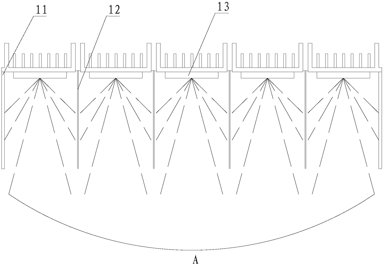
[0046] A lighting device for a stadium, at least two venues 20 to be illuminated are arranged in the stadium, and the at least two venues 20 to be illuminated are distributed in a rectangular array, and the venues 20 to be illuminated can be basketball courts, football Stadium, tennis court or badminton court, in the above-mentioned sports venues, the line of sight of competitors is parallel to the long side direction along the venue most of the time.

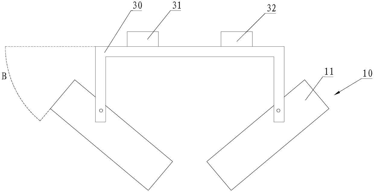
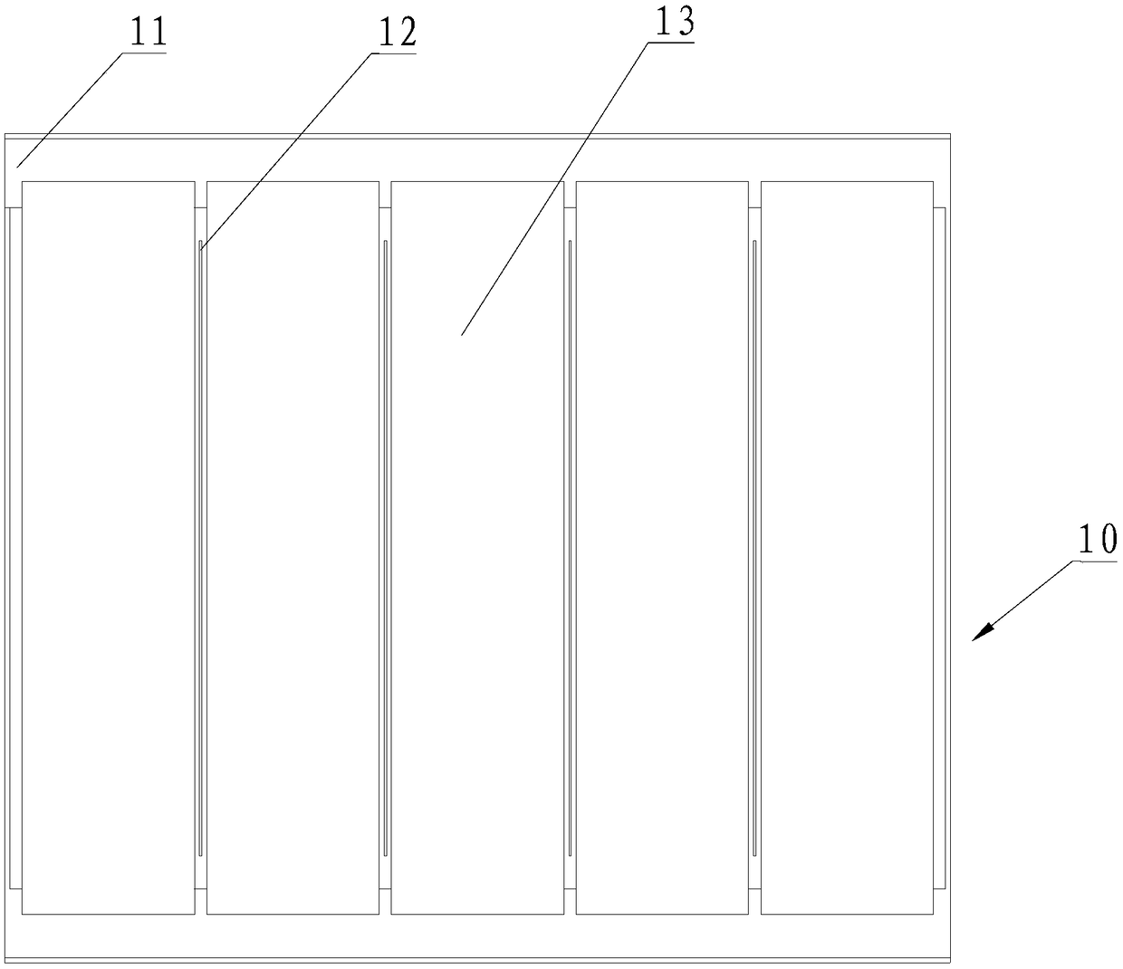
[0047] The lighting device comprises a plurality of mounting frames 20 and a plurality of lighting assemblies 10 arranged above the site to be illuminated 20, the mounting frame 30 is respectively provided with a controller 31, a power supply 32 and two lighting assemblies 10, and the two lighting assemblies The assembly 10 is arranged symmetrically, and the controller 31 is electrically connected to the power supply 32;

[0048]The mounting fram...


PUM


Abstract

The invention provides a lighting device used for the stadium. The lighting device comprises multiple lighting assemblies arranged above the site to be lighted, the lighting assemblies are arranged atintervals along the long side of the site to be lighted and are located on the two sides of the site to be lighted, each lighting assembly comprises a lamp shell, a light barrier arranged in the lampshell and a light source emitting divergent light, the light sources and the light barriers are staggered along the long side of the site to be lighted, and the light barriers and the long side of the site to be lighted are perpendicularly arranged. The light emitting direction of the lighting assemblies faces the site to be lighted. The lighting device used for the stadium can ensure the lighting quality and effectively prevents dazzling.

Description

technical field [0001] The invention relates to the technical field of lighting, in particular to a lighting device for stadiums. Background technique [0002] The focus of sports lighting design is the lighting of sports venues, which is a highly functional, highly technical and difficult design. The field lighting should meet various needs, and it should be conducive to the performance of athletes' technical level, the correct judgment of referees, and the viewing effect of all aspects in the auditorium. [0003] In sports lighting settings, most of them currently adopt horse track layout or roof matrix layout. Among them, the roof matrix arrangement will cause athletes to appear dazzled, ghosted and dizzy due to seeing the roof lights for a long time, which seriously affects the normal performance and judgment of athletes and referees. [0004] In the construction and layout of sports venues or venues, except for a few single competition purposes, most of the functions ...

Claims


Application Information

Patent Timeline
Patent Type & Authority Applications(China)
IPC IPC(8): F21S8/00F21V19/02F21V17/00
CPCF21S8/00F21V17/00F21V19/02
Inventor 赵利民张剑声林孟牢陈庆美吕鹏举
Owner FUJIAN HONGBO OPTO ELECTRONICS TECH CO LTD
Why Eureka
Try Eureka