A method for testing the wear resistance of electric detonator leg wire

A technology of wear resistance and test method, applied in the direction of testing wear resistance, etc., can solve the problems of only testing one foot line at a time, affecting the safety level of detonators, etc., and achieves compact structure design, small footprint, and simple and easy method. row effect

Active Publication Date: 2021-04-20
CHINA COAL TECH & ENG GRP HUAIBEIBLASTING TECHN RES INST
View PDF11 Cites 0 Cited by
  • Summary
  • Abstract
  • Description
  • Claims
  • Application Information

AI Technical Summary

Problems solved by technology

If the wear resistance of the electric detonator leg cannot be reasonably tested, it will seriously affect the intrinsic safety level of the detonator
The existing detonator leg wear test is mainly through manual operation, and only one leg can be tested at a time

Method used


Image

  • A method for testing the wear resistance of electric detonator leg wire
  • A method for testing the wear resistance of electric detonator leg wire
  • A method for testing the wear resistance of electric detonator leg wire

Examples


Embodiment 1

[0022] A method for testing the wear resistance of the detonator leg wire. On the wear resistance test device of the detonator leg wire, a certain action load is applied to the measured electric detonator leg wire, and it moves at a certain speed on the wear surface. , to simulate the wear force of the leg of the electric detonator under test, measure the time it takes for the insulating layer to be worn through, and evaluate the wear resistance of the leg through the time of wear.

Embodiment 2

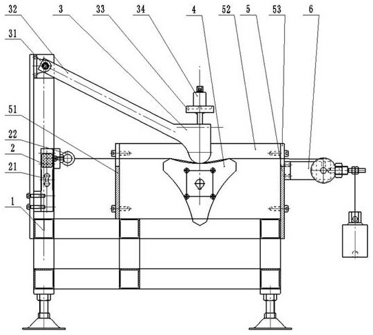
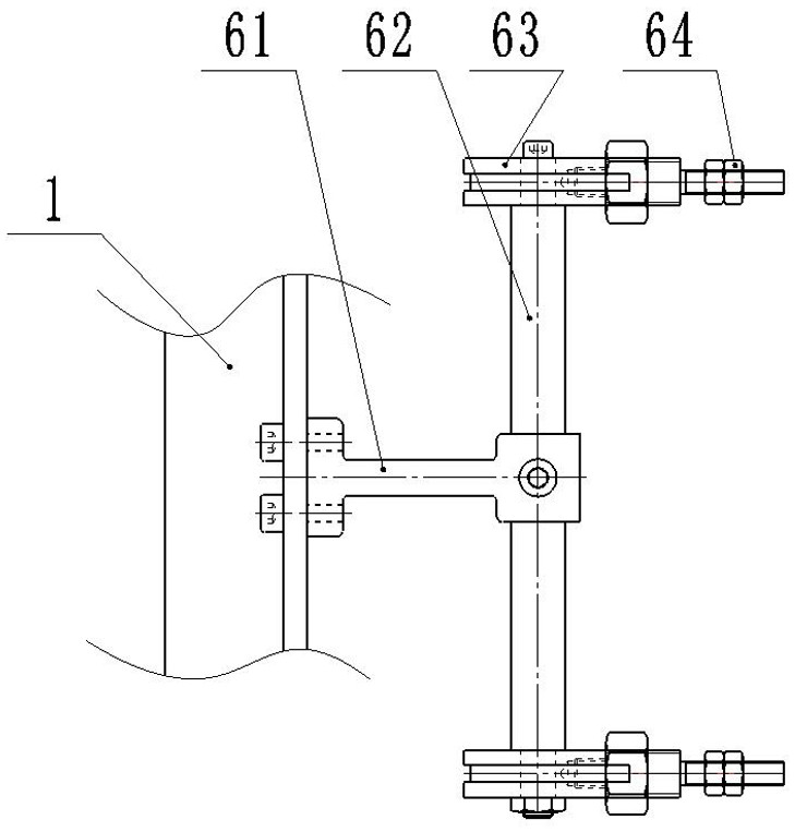
[0024] As a kind of test equipment of implementation example 1, such as figure 1 As shown, the detonator foot line wear resistance testing device includes a frame 1, a tension measuring mechanism 2 installed on the frame, a crimping mechanism 3, a rotating mechanism 4, a wire mechanism 5, and a tension adjusting mechanism 6; One end of the pin line is fixed on the tension measuring mechanism 2, the other end passes through the wire mechanism 5 and is fixed by the tension adjusting mechanism 6, and the test part of the detonator leg line to be tested is placed horizontally between the crimping mechanism 3 and the rotating mechanism 4 on the starting position.

[0025] The device for testing the wear resistance of the detonator leg line also includes a PLC control system, and the PLC control system controls components to start and stop in a logical order.

Embodiment 3

[0027] like figure 1 , figure 2 , image 3 As shown, as an optimization to Embodiment 2, the tension measuring mechanism 2 includes a gravity sensor 21, a leg fixing nut 22, the gravity sensor 21 is installed on the frame 1, and the leg fixing nut 22 is installed on the gravity sensor 21, It is used to connect one end of the leg wire of the electric detonator to be tested.

[0028] Described crimping mechanism 3 comprises pivot bar seat 31, pivot bar 32, counterweight bar 33, counterweight weight 34; Connect the counterweight bar 33, and the counterweight weight 34 is installed on the counterweight bar 33; the lower part of the connecting side of the pivot bar 32 and the counterweight bar 33 is provided with an arc grinding head, and the load is applied to the tested footline by the bar and the weight.

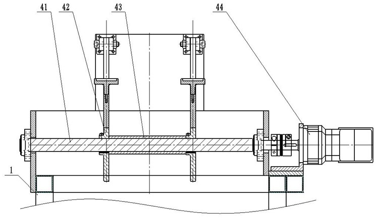
[0029] The rotating mechanism 4 includes a main shaft 41, a rotor 42, a sleeve 43, and a motor 44; the motor 44 is connected to the main shaft 41, the sleeve 43 is install...


PUM


Abstract

The invention discloses a method for testing the wear resistance of the detonator leg wire. On the wear resistance test device of the detonator leg wire, a certain action load is applied to the measured electric detonator leg wire, and the wear surface is made to wear at a certain rate. The speed movement of the measured electric detonator is simulated by the wear force, and the time it takes for the insulating layer to be worn through is measured, and the wear resistance of the foot line is evaluated by the time worn out. It also discloses the structure of the test device for the wear resistance of the electric detonator foot wire. The method of the present invention is simple and easy, the test device has a compact structure design, and occupies a small area. Cooperate, the failure rate is low, the reliability is high, and the efficiency of the wear resistance performance test of the detonator leg wire is improved at the same time.

Description

technical field [0001] The invention relates to a method and device for testing the wear resistance of electric detonator legs, which are mainly used for simulating the phenomenon that the legs of electric detonators may be worn through during the production, transportation and use of the electric detonator, and belong to the technical field of explosive detection equipment . Background technique [0002] With the rapid development of mining industry and blasting engineering, the demand for detonators is increasing. Detonators are divided into non-electric detonators and electric detonators. Electric detonators include industrial electric detonators, electronic detonators and magnetoelectric detonators. The annual output in the country is several hundred million rounds. However, the electric detonator often fails due to the damage of the foot wire. If the feet are worn through, the two feet will be short-circuited, and the detonator cannot be detonated, so the explosive ca...

Claims


Application Information

Patent Timeline
Patent Type & Authority Patents(China)
IPC IPC(8): G01N3/56
CPCG01N3/56
Inventor 杨宗玲潘先峰于魏清张志刚翟廷海李娟娟李勇岳彩新赵显莹刘伟章晋英
Owner CHINA COAL TECH & ENG GRP HUAIBEIBLASTING TECHN RES INST
Why Eureka
Try Eureka