A Bolt-Actuated Sniper Rifle Launching Mechanism Without Bolt

A firing mechanism and rifle technology, applied in the field of firearms, to achieve the effects of improving shooting comfort, improving ergonomics, and preventing accidental firing

Active Publication Date: 2020-11-20
CHONGQING JIANSHE IND GRP
View PDF8 Cites 0 Cited by
  • Summary
  • Abstract
  • Description
  • Claims
  • Application Information

AI Technical Summary

Problems solved by technology

[0005] In order to solve the technical problem of improving the ergonomics and improving the shooting accuracy of the existing non-bolt-moving sniper rifle firing mechanism, the present invention provides a non-bolt-moving sniper rifle firing mechanism

Method used


Image

  • A Bolt-Actuated Sniper Rifle Launching Mechanism Without Bolt
  • A Bolt-Actuated Sniper Rifle Launching Mechanism Without Bolt
  • A Bolt-Actuated Sniper Rifle Launching Mechanism Without Bolt

Examples


Embodiment 1

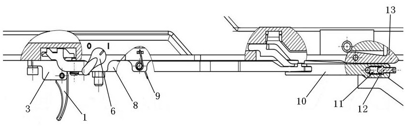
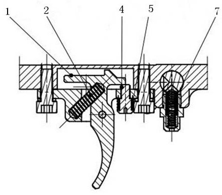
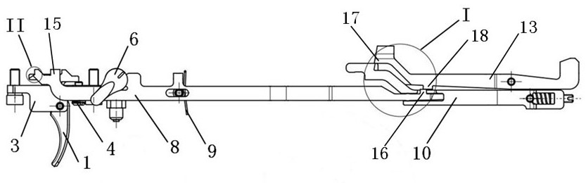
[0032] Such as Figure 1 to Figure 7As shown, the firing mechanism of a sniper rifle without a support bolt in this embodiment is characterized in that it includes a trigger 1, a trigger spring 2, a trigger seat 3, a connecting rod 8, a connecting rod spring 9, a firing rod 10, and a firing rod spring 11 and sear 13; the inner chamber of the trigger seat 3 is horizontally fixed with a trigger shaft; the trigger 1 is empty on the trigger shaft; the two ends of the trigger spring 2 are respectively in contact with the trigger 1 and the trigger seat 3; The side of the connecting rod 8 is provided with an elliptical through hole; a horizontally fixed connecting rod shaft passes through the elliptical through hole; the connecting rod spring 9 is sleeved on the connecting rod shaft and connected with the connecting rod 8 The front end of the connecting rod 8 is provided with a first boss 15; the top of the trigger 1 is provided with a first groove; the first boss 15 is located in th...

Embodiment 3

[0039] On the basis of above-mentioned embodiment, propose embodiment 3, as Figure 1 to Figure 3 As shown, it is characterized in that: the actuating sniper rifle firing mechanism without a support bolt also includes a trigger adjustment screw 4 and a trigger adjustment screw spring 5; It conflicts with the lower surface of the upper rear end of the trigger 1; the two ends of the trigger adjusting screw spring 5 are respectively connected to the trigger base 3 and the trigger adjusting screw 4.

[0040] By screwing in and out of the trigger adjustment screw 4, the size of the idle stroke of the trigger 1 can be adjusted, thereby adjusting the overall firing stroke. The trigger adjustment screw spring 5 is used to prevent the trigger adjustment screw 4 from loosening.

Embodiment 4

[0042] On the basis of above-mentioned embodiment, propose embodiment 4, as figure 1 As shown, it is characterized in that: the firing mechanism of a sniper rifle without a bolt also includes a firing rod screw 12; the firing rod spring 11 is screwed and fixed by connecting the firing rod screw 12.

[0043] By screwing in and out of the firing rod screw 12, the tightness of the firing rod spring 11 can be adjusted, thereby adjusting the firing force.


PUM


Abstract

The invention provides a support-free movable sniper rifle launching mechanism. The launching mechanism comprises a trigger (1), a trigger spring (2), a trigger seat (3), a connecting rod (8), a connecting rod spring (9), a firing rod (10), a firing rod spring (11) and an iron blocking (13); locking of the trigger (1) can drive the connecting rod (8) to move forward, the connecting rod (8) moves forwards to drive the firing rod (10) moves forwards, the firing rod (10) moves forwards to release the iron blocking (13) to complete the firing, and during resetting, the trigger (1) is reset by virtue of the trigger spring (2), the connecting rod (8) is reset by virtue of the connecting rod spring (9), and the firing rod (10) is reset by virtue of the firing rod spring (11). According to the launching mechanism, through increasing the transmission of the connecting rod (8), the trigger (1) can move forward to control the iron blocking (13), and at the same time, two firing strokes with different strength and different distances are arranged, the technical problems that for the existing support-free movable sniper rifle launching mechanism, the man-machine effect needs to be improved andthe shooting precision needs to be improved are solved.

Description

technical field [0001] The invention relates to the technical field of firearms, in particular to a firing mechanism for a sniper rifle without a bolt. Background technique [0002] The firing mechanism is the mechanism that controls the action of the firearm's firing mechanism. It is an important link in human-computer interaction and directly affects the shooting accuracy. The bullpup-action sniper rifle, due to the bullpup design, in order to ensure the ergonomic size from the shoulder to the trigger, in the firing mechanism, the trigger needs to be moved forward to the bottom of the barrel, and the sear still needs to be placed on the barrel At the rear, different from ordinary rifles, in order to increase the shooting accuracy and control the shooting time, the bolt-action sniper rifle firing mechanism needs to have two firing strokes of different lengths. [0003] However, the traditional sniper rifle firing structure is generally composed of trigger, hammer, single-s...

Claims


Application Information

Patent Timeline
Patent Type & Authority Patents(China)
IPC IPC(8): F41A19/06F41A19/12
CPCF41A19/06F41A19/12
Inventor 杨中伟顾鹏林享彬梁浩余涛徐辉
Owner CHONGQING JIANSHE IND GRP
Why Eureka
Try Eureka