Sludge flushing and filtering device

A technology for flushing and filtering sludge, which is applied in the direction of filtration and separation, sludge treatment, fixed filter element filter, etc. It can solve the problems of high impurity content, affecting sludge recovery and treatment, and the filtering device cannot filter well, etc. To achieve the effect of convenient recycling

Inactive Publication Date: 2019-04-26
江苏江澄环保设备工程有限公司
View PDF0 Cites 1 Cited by
  • Summary
  • Abstract
  • Description
  • Claims
  • Application Information

AI Technical Summary

Problems solved by technology

[0002] During the sludge purification treatment, it is necessary to wash the sludge. During the washing, the sludge can be dispersed and the impurities in the sludge can be well separated, which can make the recovery of the sludge more convenient and avoid A large amount of impurities are difficult to deal with in the sludge. During sludge treatment, flushing filter devices are used. Many filter devices cannot filter well, and the impurity content is large, which affects the further recycling of sludge.

Method used


Image

  • Sludge flushing and filtering device

Examples


Embodiment 1

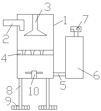
[0012] A sludge flushing and filtering device, which is provided with a filter cartridge 1, the filter cartridge 1 is provided with a sludge inlet 2, and the filter cartridge 1 is provided with a spray head 3, and the spray head 3 A water inlet pipe is provided at the upper end, and a sieve plate 4 is provided in the filter cartridge 1, and a fine mesh is provided on the sieve plate 4, and a water outlet 5 is provided on the lower side of the filter cartridge 1, and the outlet A recovery tank 6 is arranged beside the water outlet 5 .

[0013] The recovery tank 6 is a hollow structure, and a pressure control instrument 7 is arranged on the top of the recovery tank 6 .

[0014] The lower side of the filter cartridge 1 is provided with supporting legs 8 .

[0015] The lower side of the support leg 8 is provided with a mounting plate 9, and the mounting plate 9 is provided with bolt holes.

Embodiment 2

[0017] A sludge flushing and filtering device, which is provided with a filter cartridge 1, the filter cartridge 1 is provided with a sludge inlet 2, and the filter cartridge 1 is provided with a spray head 3, and the spray head 3 A water inlet pipe is provided at the upper end, and a sieve plate 4 is provided in the filter cartridge 1, and a fine mesh is provided on the sieve plate 4, and a water outlet 5 is provided on the lower side of the filter cartridge 1, and the outlet A recovery tank 6 is arranged beside the water outlet 5 .

[0018] The recovery tank 6 is a hollow structure, and a pressure control instrument 7 is arranged on the top of the recovery tank 6 .

[0019] The lower side of the filter cartridge 1 is provided with supporting legs 8 .

[0020] The lower side of the support leg 8 is provided with a mounting plate 9, and the mounting plate 9 is provided with bolt holes.

[0021] A stirring shaft 10 is arranged inside the filter cartridge 1 , and stirring blad...


PUM


Abstract

The invention discloses a sludge flushing and filtering device. The sludge flushing and filtering device is provided with a filtering cylinder provided with a sludge inlet, a spraying head is arrangedin the filtering cylinder, a water inlet pipe is arranged at the upper end of the spraying head, a sieving plate is arranged in the filtering cylinder, fine meshes are formed in the sieving plate, awater outlet is formed in the lower side of the filtering cylinder, and a recycling tank is arranged next to the water outlet. The spraying head is arranged in the filtering device, thus sludge can bediluted, impurities and the sludge can be reasonably separated, and the sludge can be recycled more conveniently; the sieving plate is arranged in the filtering cylinder, thus the sludge can be further filtered; and the recycling tank is arranged next to the water outlet, and thus the sludge can be recycled more conveniently.

Description

technical field [0001] The invention relates to a sludge filtering device, in particular to a sludge washing and filtering device. Background technique [0002] During the sludge purification treatment, it is necessary to wash the sludge. During the washing, the sludge can be dispersed and the impurities in the sludge can be well separated, which can make the recovery of the sludge more convenient and avoid A large amount of impurities are difficult to deal with in the sludge. During sludge treatment, flushing filter devices are used. Many filter devices cannot filter well, and the impurity content is large, which affects the further recovery and treatment of sludge. Contents of the invention [0003] The object of the present invention is to provide a kind of sludge flushing and filtering device with reasonable structure and high efficiency filtering. [0004] The technical solution of the present invention is: a sludge flushing and filtering device, which is provided wi...

Claims


Application Information

Patent Timeline
Patent Type & Authority Applications(China)
IPC IPC(8): B01D29/03B01D29/78C02F11/00C02F11/121
CPCB01D29/03B01D29/78C02F11/00C02F11/121C02F2303/06
Inventor 朱亮陈益民张源
Owner 江苏江澄环保设备工程有限公司
Why Eureka
Try Eureka