
Grinding-free fatigue sample strip and fatigue test method thereof
A fatigue test and grinding-free technology, which is applied in the direction of applying repetitive force/pulsation force to test the strength of materials, measuring devices, instruments, etc., can solve problems such as uneven stress distribution, impact on the accuracy of test results, and results that need to be improved to achieve Accurate effect on fatigue data
- Summary
- Abstract
- Description
- Claims
- Application Information
AI Technical Summary
Problems solved by technology
Method used
Image

Examples
Embodiment 1
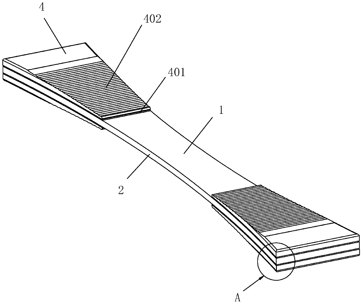
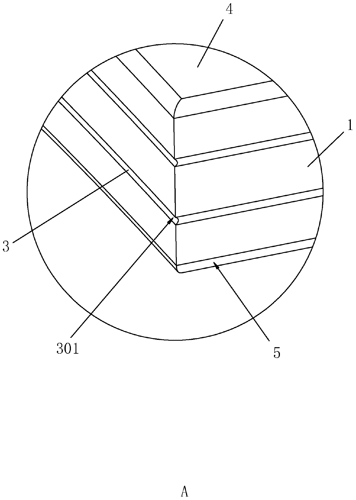
[0037] A grinding-free fatigue spline, such as figure 1 and figure 2 As shown, it includes an integral injection-molded waist body 1, the waist body 1 is in the shape of a strip, and the waists on both sides of the waist body 1 are provided with inwardly concave arcs 2, and the arcs 2 on both sides are in the shape of a shaft. Symmetrical setting. Both ends of the waist body 1 in the length direction are fixedly connected with clamping gaskets 4 through the adhesive layer 3, and the clamping gaskets 4 can be made of resin. The clamping pads 4 are located on opposite sides of the end of the waist body 1 , and the sides of the clamping pads 4 are aligned with the sides of the arc portion 2 and are also arc-shaped.
[0038] The length direction of the sides between the arc parts 2 on the clamping gasket 4 is perpendicular to the length direction of the waist body 1, and the end of the clamping gasket 4 near the center of the waist body 1 is set as a tapered end 401, gradually ...
Embodiment 2
[0042] A fatigue testing method for a grinding-free fatigue spline, comprising the steps of:
[0043] The waist body 1 in the above-mentioned grinding-free fatigue spline is prepared by injection molding.
[0044] Use the adhesive layer 3 to glue the clamping gasket 4 on both sides of the end of the waist circle body 1 in the length direction, and polish the side of the adhesive gasket to be flush with the side edge of the waist circle body 1 .
[0045] Uniformly distributed grooves 301 are ground on the side of the adhesive layer 3 .
[0046] Use fatigue testing equipment to clamp the clamping gaskets 4 at both ends of the vertically placed girdle body 1 , and use a soft abutting piece to press against the middle part of the girdle body 1 . Among them, the fatigue testing equipment first clamps the lower end of the waist body 1 placed vertically, and then clamps the upper end of the waist body 1. When the lower end is clamped but not the upper end, it can be seen whether the...
PUM
 Abstract
Description
Claims
Application Information