Distributed antenna system, remote access unit, power distribution method and medium

A distribution method and remote access technology, applied in the field of distributed antenna systems, can solve problems such as unreasonable power distribution of user terminals, and achieve the effect of reasonable power distribution

Active Publication Date: 2020-05-15
SHENZHEN UNIV
View PDF2 Cites 3 Cited by
  • Summary
  • Abstract
  • Description
  • Claims
  • Application Information

AI Technical Summary

Problems solved by technology

[0004] The main purpose of the present invention is to provide a distributed antenna system, a remote access unit, a power distribution method and a medium, aiming at solving the The problem of unreasonable power distribution

Method used


Image

  • Distributed antenna system, remote access unit, power distribution method and medium
  • Distributed antenna system, remote access unit, power distribution method and medium
  • Distributed antenna system, remote access unit, power distribution method and medium

Examples


Embodiment Construction

[0037] It should be understood that the specific embodiments described here are only used to explain the present invention, and are not intended to limit the present invention.

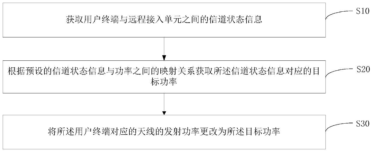
[0038] The main solution of the embodiment of the present invention is to: obtain channel state information between the user terminal and the remote access unit; obtain the target power corresponding to the channel state information according to the preset mapping relationship between the channel state information and power; changing the transmit power of the antenna corresponding to the user terminal to the target power.

[0039] Since the mapping relationship between channel state information and power is stored in the remote access unit, the remote access unit can reasonably determine the target power of the user terminal according to the mapping relationship and channel state information, thereby realizing the power of the user terminal by the remote access unit. Make a reasonable distribution.

...


PUM


Abstract

The invention discloses a power distribution method. The power distribution method comprises the steps of acquiring channel state information between a user terminal and a remote access unit; obtaining target power corresponding to the channel state information according to a preset mapping relationship between the channel state information and the power; and changing the transmitting power of theantenna corresponding to the user terminal into the target power. The invention further provides a remote access unit, a distributed antenna system and a medium. According to the invention, the powerdistribution of the remote access unit to the user terminal is reasonable.

Description

technical field [0001] The present invention relates to the technical field of communication, in particular to a distributed antenna system, a remote access unit, a power distribution method and a medium. Background technique [0002] With the rapid development of communication, the rapid increase of communication rate and energy consumption has brought great challenges to modern wireless communication networks. In recent years, researchers are constantly looking for new solutions to reform the traditional centralized antenna system (Co-located Antenna Systems, CAS) to meet the rapidly growing user needs. In addition, with the rapid development of communication systems and smart terminals, the number of smart terminals is increasing explosively, resulting in immeasurable energy consumption of future communication networks. Therefore, researchers are constantly looking for new solutions to improve spectral efficiency (Spectral efficiency, SE) and energy efficiency (Energy ef...

Claims


Application Information

Patent Timeline
Patent Type & Authority Applications(China)
IPC IPC(8): H04L5/00H04W72/04H04W72/08
CPCH04L5/0057H04W72/0473H04W72/542Y02D30/70
Inventor 钱恭斌黎柱坤何春龙曾芳艳林建圳
Owner SHENZHEN UNIV
Why Eureka
Try Eureka