Conic traverse flame tube

A technology of flame tube and tubular body, which is applied in the field of combustion chamber to achieve the effect of eliminating inhalation

Inactive Publication Date: 2003-08-27
GENERAL ELECTRIC CO
View PDF0 Cites 1 Cited by
  • Summary
  • Abstract
  • Description
  • Claims
  • Application Information

AI Technical Summary

Problems solved by technology

However, computer fluid dynamic (CFD) modeling of the purge flow showed that plugging across the flow through the tube was ineffective

Method used


Image

  • Conic traverse flame tube
  • Conic traverse flame tube
  • Conic traverse flame tube

Examples


Embodiment Construction

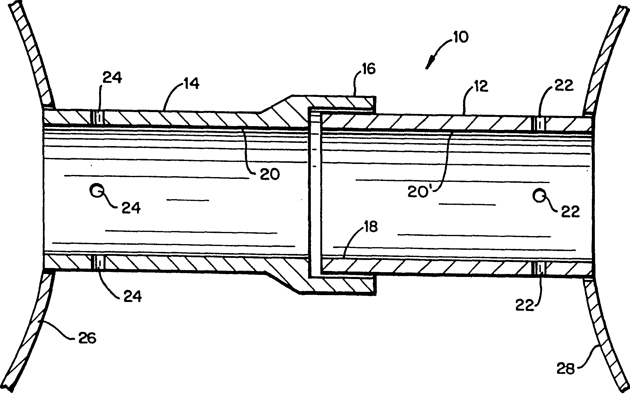
[0018] see first figure 1 A cross-fire tube 10 of conventional construction includes a generally cylindrical insert portion 12 and a generally cylindrical sleeve portion 14 having an enlarged end 16 for telescopic The free end 18 of the insertion portion 12 is received in relation thereto and is held there by any suitable means. The interior of the cross-fire tube is characterized by inner walls 20, 20' having substantially the same diameter. A plurality of air purge holes 22 , 24 are drilled in the region of each insert portion 12 and sleeve portion 14 adjacent a respective combustor liner 26 , 28 , respectively. The problems associated with this conventional cross-fire tube configuration have been described above and need not be repeated here.

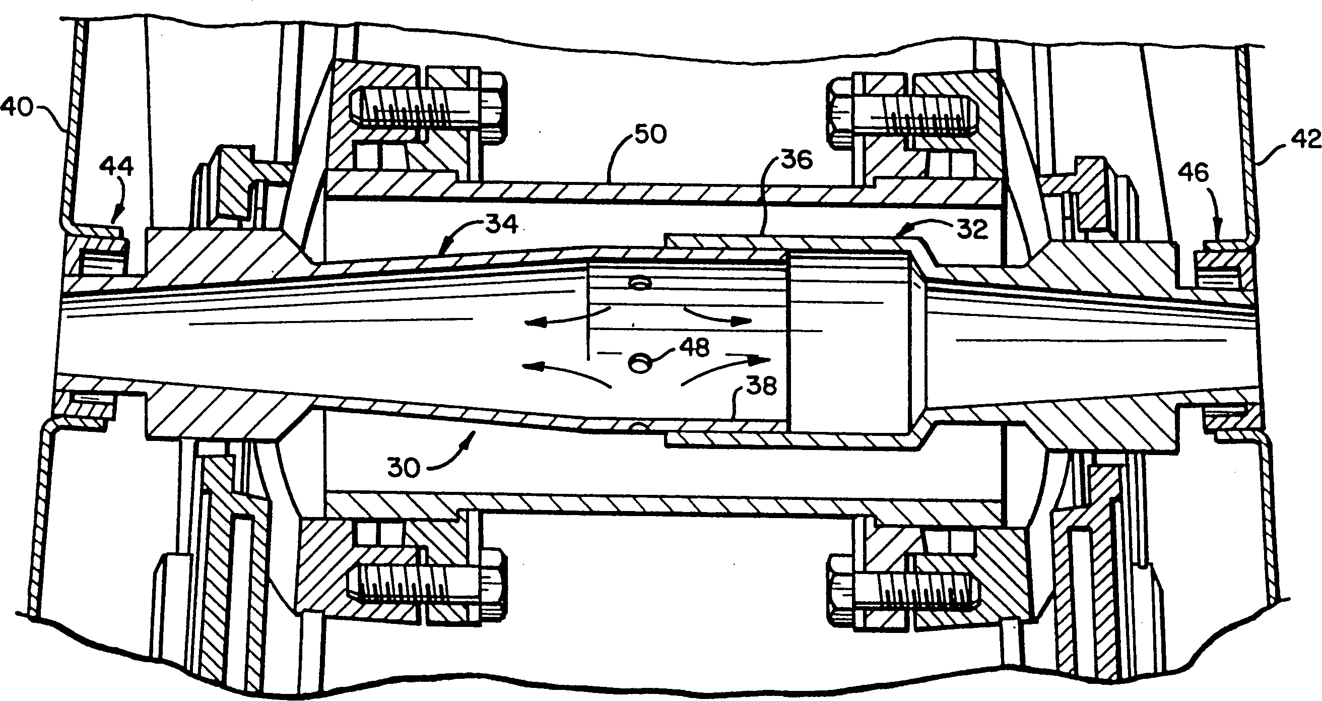
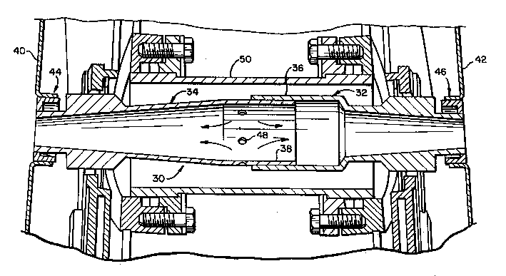
[0019] see now figure 2 A cross-fire tube according to an exemplary embodiment of the present invention includes a tubular body 30 having a sleeve portion 32 and an insert portion 34 . The sleeve portion 32 has an enlarged ...


PUM


Abstract

A cross-fire tube for connecting adjacent combustors in a gas turbine includes a hollow tubular body having couplings at opposite free ends thereof, the hollow tubular body having a substantially circular cross-sectional shape with a maximum diameter region about mid-way between the couplings, tapering in opposite directions to smaller diameters at the free ends. A plurality of purge holes are located in the maximum diameter region.

Description

technical field [0001] This invention relates to gas turbine combustors, and more specifically to a uniquely shaped cross-fire tube extending between adjacent combustors in an arrangement in which multiple combustors (or "cans") Arranged in a ring around the axial centerline of the gas turbine. Background technique [0002] The gas turbine manufactured by the present assignee is a so-called "can-ring" configuration in which 10, 14 or 18 combustors (or cans) are arranged in a ring around the axial centerline of the gas turbine. These combustion cans are isolated from each other except for cross-flame joints connected between adjacent cans. The names of these tubes allude to their function, which is that the flame traverses from one tank to the other when ignited. Existing gas turbine configurations consist of two cans equipped with ignition means (spark plugs), while ignition of the other can is by means of a flame from an adjoining ignited can through a traversing flame tu...

Claims


Application Information

Patent Timeline
Patent Type & Authority Patents(China)
IPC IPC(8): F23R3/48
CPCF23R3/48
Inventor S·H·布拉克J·L·巴塔利奥利W·T·贝特尔二世
Owner GENERAL ELECTRIC CO
Why Eureka
Try Eureka