Spiral chain discarding device capable of quickly reacting

A fast response and chain abandoner technology, which is applied in shipbuilding, mooring equipment, ships, etc., can solve the problems of misoperation of chain abandoner, inability to quickly separate the hull from the anchor chain, and long time for screw separation and unscrewing. , to achieve the effect of avoiding false touch

Active Publication Date: 2020-11-27
李茹茹
View PDF5 Cites 4 Cited by
  • Summary
  • Abstract
  • Description
  • Claims
  • Application Information

AI Technical Summary

Problems solved by technology

[0003] However, the traditional screw chain abandoner still has the following deficiencies in the actual use process: first, in the actual use process, when the anchor chain needs to be unchained, it is necessary to manually rotate the handle multiple times to perform the chain abandonment operation. There are many requirements for the number of rotations of the screw, and it takes a long time for the screw to be separated and unscrewed in the adjustment seat, so that when a sudden accident occurs in the hull and needs to be transferred quickly, the hull and the anchor chain cannot be separated quickly; secondly, because the screw chain discarder Most of them are installed on the bulkhead of the chain locker or on the deck, which is an easy-to-reach position for the crew on board, which leads to the possibility of accidental touch, and it is easy to cause misoperation of the chain discarder, so that the anchor and anchor chain will be damaged due to people's actions. Misoperation and was discarded into the sea, causing unnecessary losses

Method used


Image

  • Spiral chain discarding device capable of quickly reacting
  • Spiral chain discarding device capable of quickly reacting
  • Spiral chain discarding device capable of quickly reacting

Examples


Embodiment Construction

[0018] The following will clearly and completely describe the technical solutions in the embodiments of the present invention with reference to the accompanying drawings in the embodiments of the present invention. Obviously, the described embodiments are only some, not all, embodiments of the present invention. Based on the embodiments of the present invention, all other embodiments obtained by persons of ordinary skill in the art without making creative efforts belong to the protection scope of the present invention.

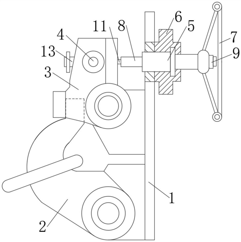
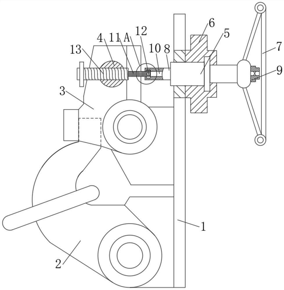
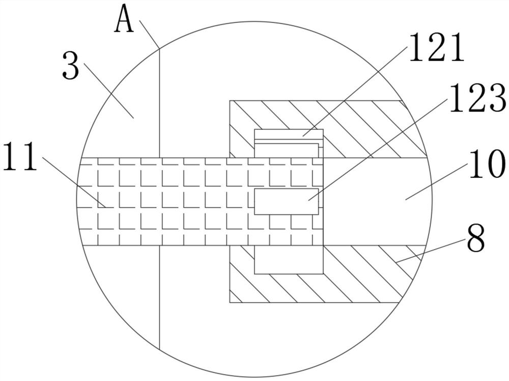
[0019] see Figure 1-4 , a fast-response spiral chain discarder, comprising a mounting plate 1, a chain hook 2 is hinged on one side of the bottom of the mounting plate 1, an adjusting seat 3 is hinged on one side of the middle of the mounting plate 1, and the upper part of the adjusting seat 3 is movably socketed There is a rotating shaft 4, the upper end of the mounting plate 1 is movably socketed with a connecting shaft 5, the outer side of the connecting s...


PUM


Abstract

The invention relates to the technical field of ship equipment and discloses a spiral chain discarding device capable of quickly reacting. The device comprises a mounting plate, a chain hook is hingedto one side of the bottom of the mounting plate, an adjusting seat is hinged to one side of the middle of the mounting plate, and a rotating shaft is movably connected to the upper portion of the adjusting seat in a sleeving mode. Through the arrangement of an adjusting device and a channel, when an anchor chain is clamped, a worker rotates an adjusting handle clockwise to clamp the chain hook; when an accident occurs and emergency chain discarding is needed, a worker can manually rotate the adjusting handle anticlockwise; at the moment, the hollow shaft drives a clamping block to reversely rotate; fixing teeth rotate to extrude the clamping block to shrink towards the interior of the sleeve shaft; the clamping block can be completely pressed in only by rotating one eighth circle, at themoment, due to the influence of factors such as the gravity of the anchor chain, the sleeve shaft enters along the channel, the bottom end of the adjusting base can be rapidly and automatically liftedup for chain discarding, and compared with a traditional spiral chain discarding device, rapid chain discarding can be automatically conducted.

Description

technical field [0001] The invention relates to the technical field of ship equipment, in particular to a quick-response spiral chain discarder. Background technique [0002] The chain abandoner is a special device that quickly separates the end of the anchor chain from the hull in an emergency. It is generally installed at a place that is easily accessible to personnel on the ship or on the bulkhead of the chain locker, and is connected to the chain abandonment device through the chain end link. . The chain discarder should be able to ensure that the anchor chain can be quickly and reliably released in an emergency. The common chain discarders include horizontal bolt type chain discarder and spiral chain discarder, etc. Among them, the spiral chain discarder is operated by handwheel The chain hook is loosened or clamped by the expansion and contraction of the screw rod. Its structure is relatively complicated, but it is safe and reliable to use, and it is not easy to loose...

Claims


Application Information

Patent Timeline
Patent Type & Authority Applications(China)
IPC IPC(8): B63B21/00B63B21/22
CPCB63B21/00B63B21/22B63B2021/004
Inventor 李茹茹
Owner 李茹茹
Why Eureka
Try Eureka