terminal block connector

A terminal block and connector technology, which is applied in the direction of connection, parts of the connection device, contact parts, etc., can solve problems such as short circuit and complex structure, and achieve the effects of preventing accidental touch, simple structure, and convenient installation

Active Publication Date: 2022-03-22
SHANGHAI GONQI ELECTRIC CO LTD
View PDF7 Cites 0 Cited by
  • Summary
  • Abstract
  • Description
  • Claims
  • Application Information

AI Technical Summary

Problems solved by technology

[0003] At present, the wire mounting parts and the switch control mechanism of the terminal block connector are usually located in one chamber, the structure is complex, and it is easy to cause risks such as short circuit

Method used


Image

  • terminal block connector
  • terminal block connector
  • terminal block connector

Examples


Embodiment 1

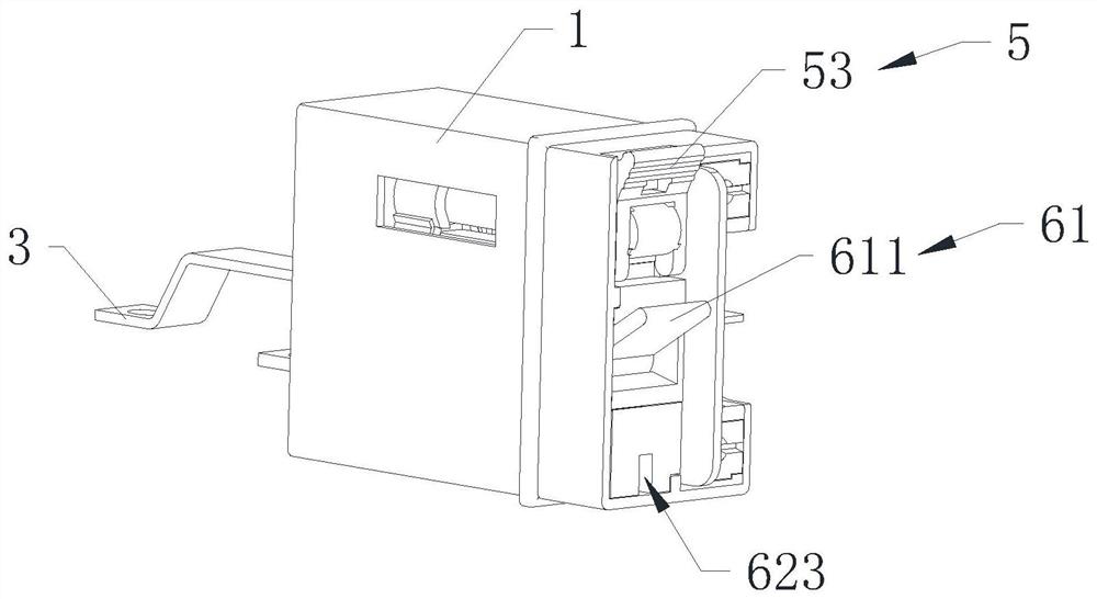
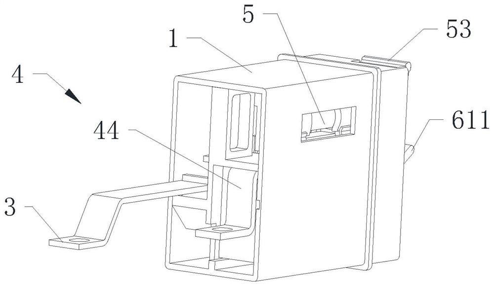
[0059] Reference manual attached Figure 1 to Figure 13 , The present invention provides a terminal connector, the terminal connector is simple in structure, small in size and easy to use.

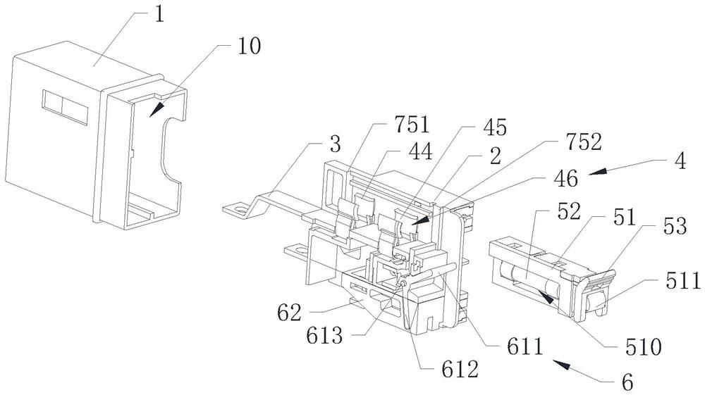
[0060] Reference manual attached figure 1 , figure 2 , image 3 as well as Figure 4 , specifically, the terminal connector includes a connector housing 1 , a separation seat 2 , a first conductive member 3 , a second conductive component 4 , a fuse 5 and a switch component 6 . The connector housing 1 surrounds an accommodating cavity 10 . The separation seat 2 is installed in the accommodation chamber 10 and divides the accommodation chamber 10 into an operation chamber 11 and a wiring chamber 12 . The first conductive member 3 is installed in the wiring cavity 12 for electrical connection with the first electric wire.

[0061] The second conductive component 4 includes a second conductive member 41 , a movable contact conductive member 42 , a static contact conductive member 43 , ...


PUM


Abstract

The invention discloses a wiring terminal connector, which comprises: a connector housing surrounding and forming an accommodating cavity; a partition seat installed in the accommodating cavity and separating the accommodating cavity into a control cavity and a wiring cavity; a first conductive member, a first One end of the conductive part is installed in the wiring cavity; the second conductive component includes the second conductive part, the movable contact conductive part, the static contact conductive part, the first fuse clip, the second fuse clip and the connecting wire; The second conductive part is installed in the wiring cavity, the movable contact conductive part, the static contact conductive part, the first fuse clip, and the second fuse clip are arranged in the operating cavity; the static contact conductive part is electrically connected to the second fuse Clip, one end of the conductive wire is electrically connected to the second conductive part, and the other end is electrically connected to the movable contact conductive part; the fuse is installed in the operating chamber; the switch assembly is installed in the operating chamber; the crimping assembly is installed in the wiring chamber . The wiring cavity is separated from the control cavity, with simple structure and high stability.

Description

technical field [0001] The invention relates to the field of switches, and further relates to a fuse type terminal connector. Background technique [0002] Terminal block connectors are common electronic accessories in the electromechanical field and are widely used in life and production. Between the blocked or isolated circuits in the circuit, the terminal block connector is a bridge for communication, which can make the current flow and make the circuit realize the predetermined function. It is an indispensable part of electronic equipment. [0003] At present, the wire mounting parts and the switch control mechanism of the terminal block connector are usually located in a chamber, and the structure is complex, which is easy to cause risks such as short circuit. [0004] To sum up, it is necessary to improve the traditional terminal blocks. Contents of the invention [0005] In view of the above technical problems, the purpose of the present invention is to provide a ...

Claims


Application Information

Patent Timeline
Patent Type & Authority Patents(China)
IPC IPC(8): H01R13/502H01R13/70H01R13/02H01R13/688
CPCH01R13/502H01R13/70H01R13/02H01R13/688
Inventor 林汉书曾国静
Owner SHANGHAI GONQI ELECTRIC CO LTD
Why Eureka
Try Eureka