Direct current electric equipment speed control method, control device and direct current electric equipment
A technology of electric equipment and speed control, which is used in the control of workpiece feed movement, metal processing equipment, grinding/polishing equipment, etc., can solve the problem that the output speed of the angle grinder cannot reach the set speed of full power, which affects the use of users. experience, etc.
- Summary
- Abstract
- Description
- Claims
- Application Information
AI Technical Summary
Problems solved by technology
Method used
Image

Examples
Embodiment 1
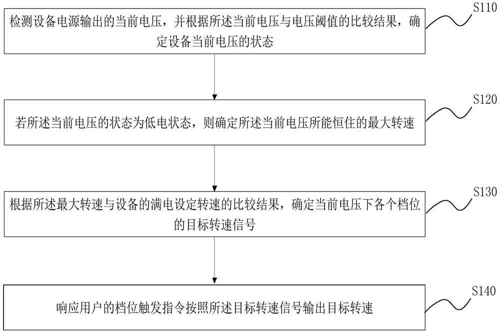
[0023] figure 1 It is a flow chart of a method for controlling the speed of a DC electric device provided by Embodiment 1 of the present invention. This embodiment is applicable to the situation where the speed of a DC-powered electric device is adjusted when the power is low. When the angle grinder is in a semi-electric state, it is necessary to re-determine the speed of each gear, so that the gear will be output at the set level from high to low under the current voltage. This method can be implemented by software or hardware, for example , executed by a processor storing an execution program, the method specifically includes the following steps:
[0024] S110. Detect the current voltage output by the power supply of the device, and determine the state of the current voltage of the device according to a comparison result between the current voltage and a voltage threshold.
[0025] Among them, due to the use and consumption of the equipment, the output voltage of the equipm...
Embodiment 2
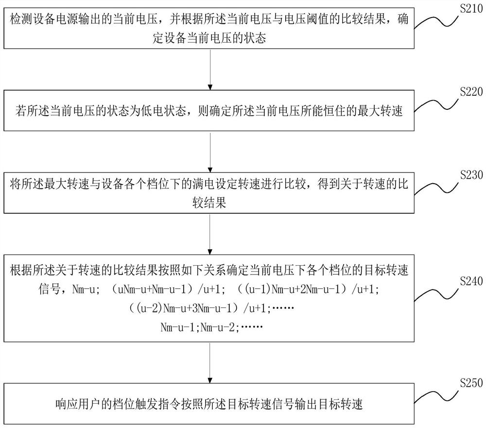
[0045] figure 2 It is a flow chart of a method for controlling the speed of a DC electric device provided in Embodiment 2 of the present invention. This embodiment optimizes the method for determining the speed on the basis of the above-mentioned embodiments. The method specifically includes the following steps:
[0046] S210. Detect the current voltage output by the power supply of the device, and determine the state of the current voltage of the device according to a comparison result between the current voltage and a voltage threshold.
[0047] S220. If the state of the current voltage is a low power state, determine a maximum rotational speed that the current voltage can sustain.
[0048] S230. Comparing the maximum rotation speed with the set rotation speed at full power in each gear of the device to obtain a comparison result about the rotation speed.
[0049] Among them, the device has a full-power set speed corresponding to each gear. After determining the maximum sp...
Embodiment 3
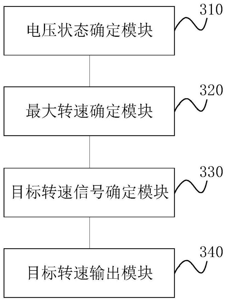
[0063] image 3 A schematic structural diagram of a speed control device for DC electric equipment provided by Embodiment 3 of the present invention, which can be configured in electric equipment. This embodiment is applicable to adjusting the speed of electric equipment when DC-powered electric equipment is used at low power situation, such as image 3 As shown, the device specifically includes: a voltage state determination module 310, a maximum rotational speed determination module 320, a target rotational speed signal determination module 330, and a target rotational speed output module 340, wherein:
[0064] The voltage state determination module 310 is configured to determine the current voltage state of the device according to the comparison result of the current voltage output by the power supply of the device and the voltage threshold.
[0065] Optionally, the voltage state determination module 310 is specifically used for:
[0066] Compare the current voltage with ...
PUM
 Abstract
Description
Claims
Application Information
 - R&D
- Intellectual Property
- Life Sciences
- Materials
- Tech Scout
- Unparalleled Data Quality
- Higher Quality Content
- 60% Fewer Hallucinations
Browse by: Latest US Patents, China's latest patents, Technical Efficacy Thesaurus, Application Domain, Technology Topic, Popular Technical Reports.
© 2025 PatSnap. All rights reserved.Legal|Privacy policy|Modern Slavery Act Transparency Statement|Sitemap|About US| Contact US: help@patsnap.com