Lens group, camera module, and imaging system

A camera module and imaging system technology, which is applied in the field of optical lenses, can solve problems such as lack of correction capabilities, and achieve the effects of improving effective recognition, avoiding collisions, and improving reliability

Active Publication Date: 2021-05-11
NINGBO SUNNY AUTOMOTIVE OPTECH
View PDF5 Cites 1 Cited by
  • Summary
  • Abstract
  • Description
  • Claims
  • Application Information

AI Technical Summary

Problems solved by technology

It is not difficult to see that the image formed on the imaging surface of a lens using a traditional optical lens has a symmetrical property, so it does not have the ability to correct the above situation

Method used


Image

  • Lens group, camera module, and imaging system
  • Lens group, camera module, and imaging system
  • Lens group, camera module, and imaging system

Examples


Embodiment 1

[0078] The following reference Figure 5A to Figure 6B The camera module 100 according to Embodiment 1 of the present application will be described.

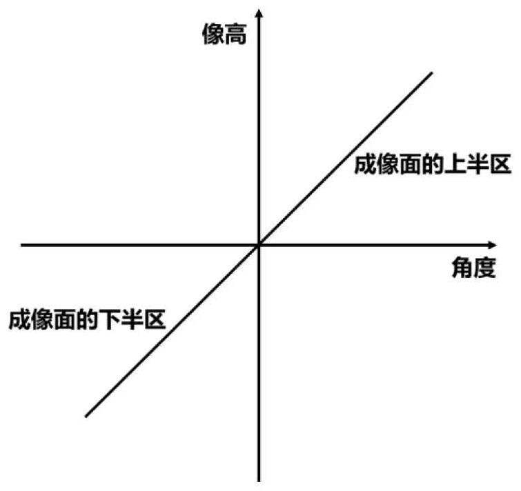
[0079] The camera module 100 may include a lens group 110 having one or more lenses. The lens group 110 may include free-form lenses with non-rotationally symmetrical mirror surfaces. By adjusting the structure and optical parameters of the free-form surface lens, the camera module 100 has the following characteristics: Figure 5A The image shown is the high angle curve.

[0080] The imaging area of ​​the camera module 100 is as Figure 5B shown. The imaging area is divided into imaging area I and imaging area II. The imaging area I and the imaging area II are sequentially distributed in a first direction perpendicular to the optical axis of the lens group 110 . In the imaging area I, the slope of the high-angle curve of the image decreases, and the image is reduced; while in the imaging area II, the slope of the high-angl...

Embodiment 2

[0089] Refer to the following Figure 7A with Figure 7B A camera module 100 according to Embodiment 2 of the present application will be described. In this embodiment and the following embodiments, for the sake of brevity, descriptions similar to those in Embodiment 1 will be omitted.

[0090] The camera module 100 may include a lens group 110 having one or more lenses. The lens group 110 may include free-form lenses with non-rotationally symmetrical mirror surfaces. By adjusting the structure and optical parameters of the free-form surface lens, the camera module 100 has the following characteristics: Figure 7A The image shown is the high angle curve.

[0091] The imaging area of ​​the camera module 100 is as Figure 7B shown. The imaging area is divided into imaging area I, imaging area II and imaging area III. In the imaging area I, the slope of the image high-angle curve decreases, and the image is reduced; in the imaging area II, the slope of the image high-angle...

Embodiment 3

[0096] The following reference Figure 8A with Figure 8B A camera module 100 according to Embodiment 3 of the present application will be described.

[0097] The camera module 100 may include a lens group 110 having one or more lenses. The lens group 110 may include free-form lenses with non-rotationally symmetrical mirror surfaces. By adjusting the structure and optical parameters of the free-form surface lens, the camera module 100 has the following characteristics: Figure 8A The image shown is the high angle curve.

[0098] The imaging area of ​​the camera module 100 is as Figure 8B shown. The imaging area is divided into imaging area I, imaging area II and imaging area III. In imaging area I, the slope of the image height angle curve increases, and the image is enlarged; in imaging area II, the slope of the image height angle curve decreases, and the image is reduced; while in imaging area III, the slope of the image height angle curve increases, and the image is ...


PUM


Abstract

The invention discloses a lens group, a camera module and an imaging system. The lens group according to an exemplary embodiment is configured to be coupled with an image sensor, and light from outside passing through the lens group forms an image on the image sensor, in which the lens group includes a free-form lens having a non-rotationally symmetric mirror surface such that the image formed on the image sensor has a first imaging region and a second imaging region. The first imaging region and the second imaging region have different zoom magnifications from each other. The camera module according to an exemplary embodiment includes the lens group as described above. The imaging system includes the camera module having a lens group and a display module.

Description

technical field [0001] The present application relates to the field of optical lenses, and more specifically, to a camera module suitable for a vehicle rearview lens and a vehicle imaging system including the camera module. Background technique [0002] At present, with the maturity of assisted driving technology, vehicle assisted driving functions for assisting parking and so on have become popular. In order to obtain information such as road conditions and pedestrians around the vehicle, it is necessary to use optical lenses such as rear-view lenses and surround-view lenses to capture image information of the ground and objects on the ground within a certain range. In particular, parking assistance functions need to focus on distant objects or pedestrians in order to avoid undesired collisions. Therefore, the image sharpness and scaling of the corresponding imaged portion on the chip is important. [0003] However, the traditional optical lens has the characteristic that...

Claims


Application Information

Patent Timeline
Patent Type & Authority Applications(China)
IPC IPC(8): H04N5/225G02B13/00B60R1/00
CPCG02B13/002G02B13/0045G02B13/006B60R1/00H04N23/55
Inventor 王一峰谢前森
Owner NINGBO SUNNY AUTOMOTIVE OPTECH
Why Eureka
Try Eureka