Cutter

A cutting and cutting part technology, applied in the field of cutting devices, can solve problems such as single straight line cutting function, and achieve the effect of increasing functions and improving single functions

Inactive Publication Date: 2004-01-07
YUDONG PLASMA TECH
View PDF0 Cites 0 Cited by
  • Summary
  • Abstract
  • Description
  • Claims
  • Application Information

AI Technical Summary

Problems solved by technology

[0005] The main purpose of the present invention is to provide a cutting device, which has the functions of linear cutting and circular cutting at the same time, so as to improve the shortcomings of the single linear cutting function of traditional paper cutters.

Method used


Image

  • Cutter
  • Cutter
  • Cutter

Examples


Embodiment Construction

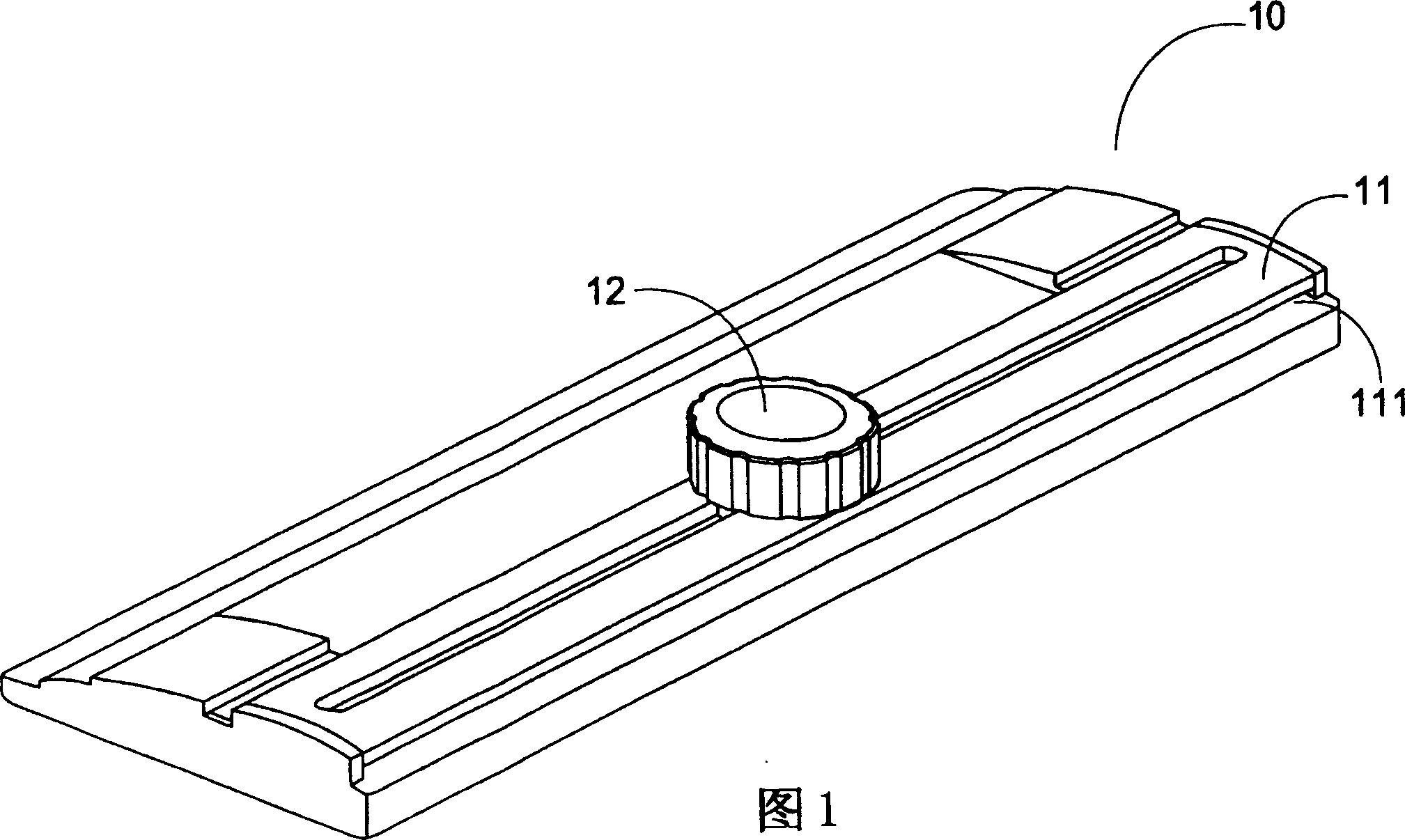
[0025] Such as image 3 As shown, the cutting device 3 of the present invention is mainly used for cutting a flat material (not shown), and the cutting device 3 at least includes a slide rail 31 , a cross bar 32 and an object 33 . Wherein the bottom of the slide rail 31 has a space 311 in order to provide the placement of the plane material, and the crossbar 32 has a cutting portion 321 for cutting the plane material, in addition, the object 33 passes through the slide rail 31 and is connected to the plane material. The crossbar 32 is connected. When cutting, provide a pressure to the object 33 and make the slide rail 31 suppress the plane material, and the object 33 moves along the slide rail 31, driving the cutting portion 321 of the cross bar 32 to perform straight cutting . In addition, by moving the object 33 along the slide rail 31 in a state where the cutting portion 321 is not in contact with the planar material, its working position can be changed, and on different ...


PUM


Abstract

The cutter for cutting planar material includes one slide rail with some space below it the planar material to be set; one cross bar with one cutting unit for cutting the planar material; and one target connected via the slide rail to the cross bar. When the target is moved along the slide rail. The cutting unit of the cross bar is driven to move; and when the target is rotated, the cutting unit of the cross bar is driven to perform arced cutting.

Description

technical field [0001] The invention relates to a cutting device, in particular to a cutting device for cutting a plane material such as paper. technical background [0002] With the progress and development of the times, the convenience and multi-functionality of products have gradually become important considerations for ordinary consumers when purchasing products. Most consumers will tend to buy multi-functional products in order to maximize economic benefits. Therefore, the industry continues to design various multi-functional products, such as telephones with answering and answering functions, fax machines with copying functions, mobile phones with short message functions, and so on. However, as far as the current technology is concerned, the paper cutters used in general offices or affairs can only perform straight line cutting and cannot provide other additional functions, so that many equipments are left idle and wasted. [0003] As shown in Figure 1, it is a struc...

Claims


Application Information

Patent Timeline
Patent Type & Authority Patents(China)
IPC IPC(8): B26D5/38
Inventor 范育硕克利斯佛斯托克曾子峯
Owner YUDONG PLASMA TECH
Why Eureka
Try Eureka