Tracheostomy tube

A tracheotomy and endotracheal technology, applied in tracheal intubation, medical science, respiratory masks, etc., can solve the problems that patients cannot make sounds and air cannot be sent to the vocal cords

Inactive Publication Date: 2003-08-06
野守裕明
View PDF0 Cites 5 Cited by
  • Summary
  • Abstract
  • Description
  • Claims
  • Application Information

AI Technical Summary

Problems solved by technology

Since the vocal cords are located between the trachea and the mouth, the patient cannot make a sound using the existing tracheostomy tube, which cannot send air to the vocal cords

Method used


Image

  • Tracheostomy tube
  • Tracheostomy tube
  • Tracheostomy tube

Examples


Embodiment Construction

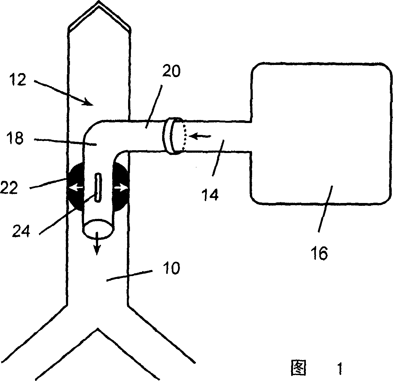
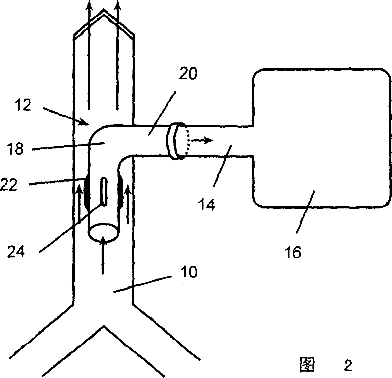
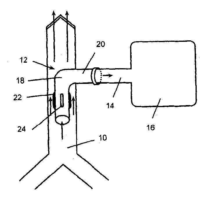
[0010] Figures 1 and 2 show a tracheostomy tube 12 according to a preferred embodiment of the present invention placed in a patient's trachea 10 . What Fig. 1 represented was the state of inhalation, and what Fig. 2 represented was the state of exhalation.

[0011] The tracheotomy tube 12 is connected to an artificial respirator 16 through a communication tube 14 .

[0012] The tracheostomy tube 12 has an inner tube portion 18 disposed in the trachea, an outer tube portion 20 connected to the artificial respirator 16, and a balloon 22 disposed on the entire circumference outside the inner tube portion.

[0013] The airbag 22 is mounted on the outer wall over the entire circumference of the inner tube portion 18 at upper and lower portions of the airbag 22 in such a manner that the inside and the outside cannot communicate with each other, for example, with adhesive or the like.

[0014] The inner tube portion 18 has a hole 24 communicating the inside of the inner tube portion...


PUM


Abstract

Provided is a tracheostomy tube enabling speech. The tube is provided with an inside tube portion to be set in a trachea, an outside tube portion to connected to a ventilator, and a balloon set on the circumference of the outside of the inside tube portion, in which the balloon is set to the inside tube portion so that the inside and outside of the balloon cannot communicate with each other and the inside tube portion has a hole for communicating the inside of the inside tube portion with the inside of the balloon.

Description

technical field [0001] The present invention relates to tracheostomy tubes, and more particularly to tracheostomy tubes in which the patient can make sounds. Background technique [0002] Generally, artificial respiration using a tracheotomy tube is to cut the trachea in the neck, put the tube with the air bag into the trachea, and connect it to the artificial respirator, and then inject air into the air through the tube connected to the air bag. Send air, etc., so that the air bag is crimped and tightly attached to the inner wall of the trachea, so that oxygen or air will not flow into the mouth, and the oxygen or air will be sent in with an artificial respirator. [0003] When using this method, the space between the trachea and the tube is closed by continuously inflating the air bag, so that the exhaled and inhaled air can only pass between the artificial respirator and the lungs. If this is not the case, most of the air will not reach the lungs when it is introduced, b...

Claims


Application Information

Patent Timeline
Patent Type & Authority Applications(China)
IPC IPC(8): A61M16/06A61M16/04
CPCA61M16/0465A61M16/0452
Inventor 野守裕明
Owner 野守裕明
Why Eureka
Try Eureka