Voltage control oscillator with low phase noise

A voltage-controlled oscillator and phase noise technology, which is applied to power oscillators, electrical components, etc., can solve problems such as improving and degrading oscillator phase noise

Inactive Publication Date: 2003-10-22
MEDIATEK INC
View PDF1 Cites 26 Cited by
  • Summary
  • Abstract
  • Description
  • Claims
  • Application Information

AI Technical Summary

Problems solved by technology

However, since the noise at the output of the bias circuit 14 can be amplified by the even-order harmonics through the transistors Q1 and Q2, the relative noise level (Noise Level) is increased
This feature relatively degrades the phase noise of the oscillator

Method used


Image

  • Voltage control oscillator with low phase noise
  • Voltage control oscillator with low phase noise
  • Voltage control oscillator with low phase noise

Examples


Embodiment Construction

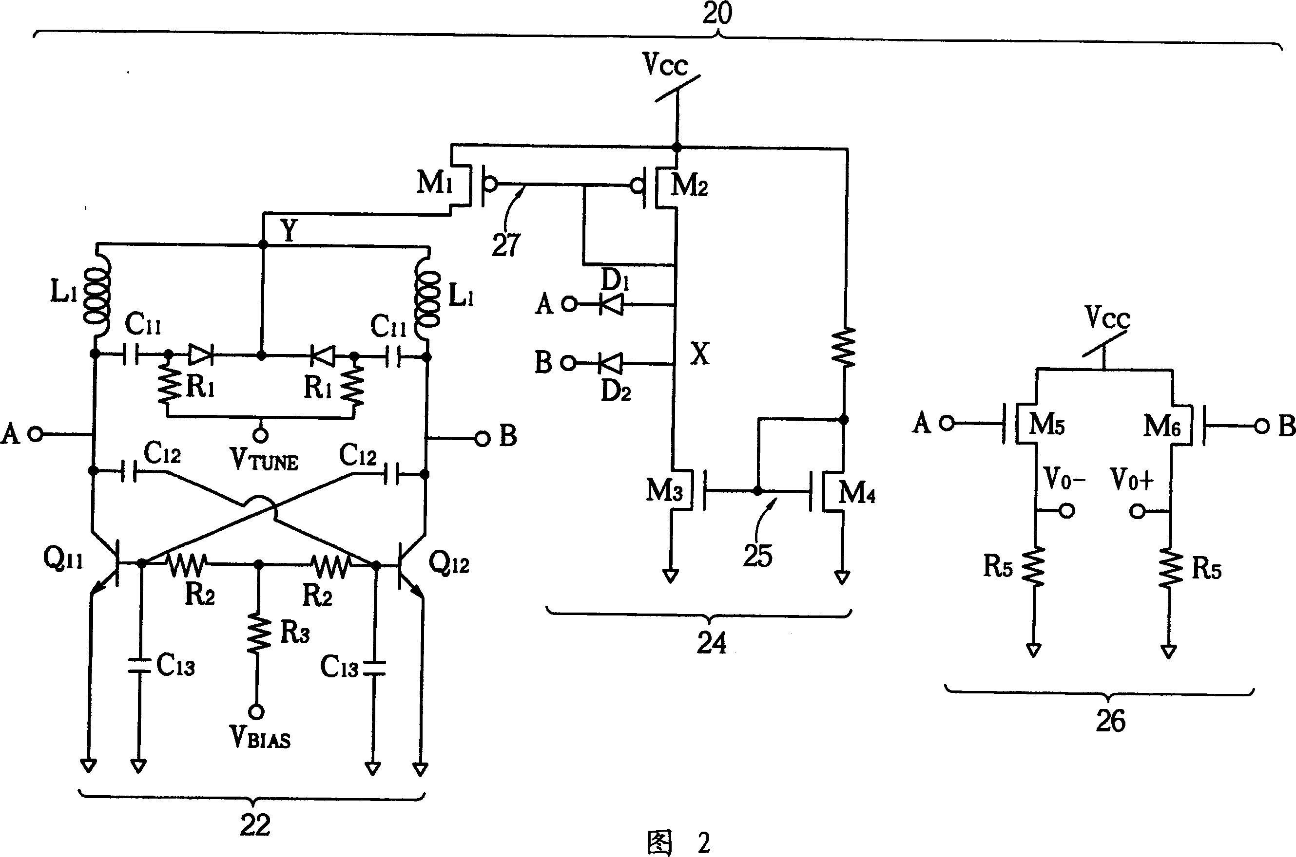
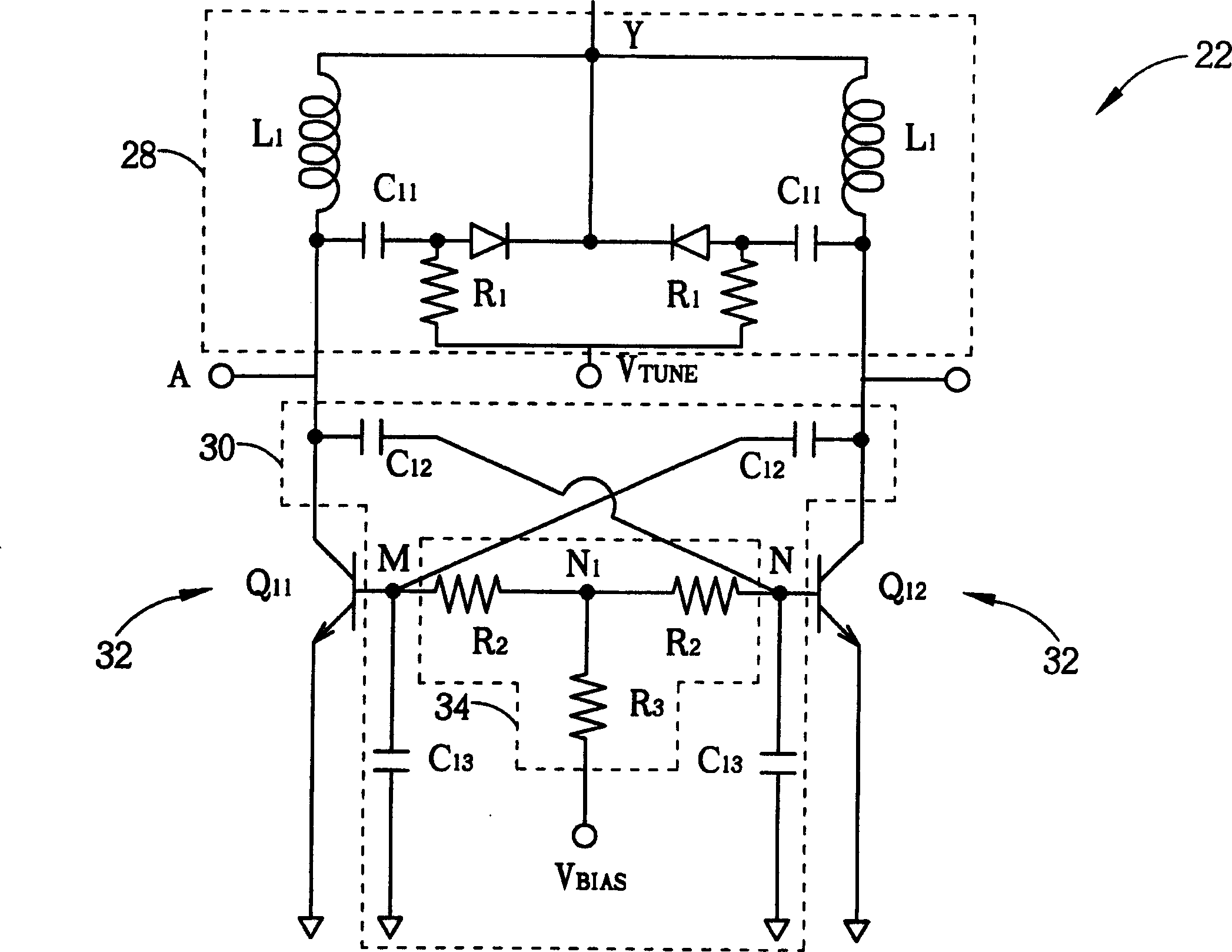
[0022] Please refer to Figure 2 with image 3 . FIG. 2 is a circuit diagram of a voltage controlled oscillator (voltage control loscillator, VCO) 20 of the present invention. image 3 is a circuit diagram of an oscillator core 22 in the voltage-controlled oscillator 20 . The oscillation circuit 22 includes a tunable-frequency LC tank (tunable-frequency LC tank) 28 that can modulate the oscillation frequency and a negative resistance generator (negative resistance generator) 32. The negative resistance generator 32 can be used to amplify the LC tank 28. The positive feedback circuit of the sine wave (positive feedback circuit). The base bias of the transistors Q11 and Q12 in the negative resistance generator 32 is provided by a T-type resistor circuit 34 .

[0023] The T-shaped resistor circuit 34 includes two first resistors R2a, R2b and one second resistor R3. One end of the first resistor R2a, R2b is respectively connected to the base of the bipolar junction transistor Q...


PUM


Abstract

This invention provides a voltage controlled oscillator with low phase noise containing a LC resonant loop, a negative resistance generation circuit and a noise suppression loop including a T(or delta) base bias resistant circuit, the said noise suppression loop is for reducing the noise of the said voltage-controlled oscillator and improving its phase noise performance.

Description

technical field [0001] The invention provides an oscillator, in particular to an oscillator circuit structure capable of reducing the phase noise in the oscillator and improving the signal-to-noise ratio of the oscillator. Background technique [0002] High frequency differential voltage controlled oscillator (VCO) has been widely used in various communication systems, and this type of voltage controlled oscillator can be applied to integrated circuits, and even communication systems can achieve Light, thin, and short are required, and the quality of a voltage-controlled oscillator depends on whether it has low phase noise (phase noise) and high signal-to-noise ratio (SNR). [0003] Please refer to figure 1 , figure 1 is a circuit diagram of a known oscillator 10 disclosed in US Pat. No. 6,064,277. The oscillator 10 uses a drive circuit 12 to drive an LC tank 11 . The LC resonant tank 11 includes an inductor L and a capacitor C for generating sinusoidal waves. The drivi...

Claims


Application Information

Patent Timeline
Patent Type & Authority Applications(China)
IPC IPC(8): H03B1/04H03B5/12
CPCH03B5/1243H03B2202/042H03B5/1215H03B5/1231H03B1/00
Inventor 黄尊禧
Owner MEDIATEK INC
Why Eureka
Try Eureka